Although in the eyes of the man in the street the thermionic valve is probably associated a 'almost entirely' with the science of radio communication - hence the common term 'wireless valve' - it is appreciated in technical circles that the limitations of its application by no means end with this field. In spite of this, few except specialists, realise how many types of valves have appeared during the past few years, incorporating designs aimed principally at the industrial or laboratory application.
The versatility of the modern thermionic valve, and the improvements in cathode technique, methods of obtaining high vacua and high insulation, and experiments in gas-filling, offer an ever-expanding scope for the ingenuity of electrical engineers and scientists.
A great deal more attention has been paid in America to the applications of valves in industry and science than in this country, and surveys have been issued for a large number of practical applications, many of which are in actual daily use. [★] See Electronics January, 1935. A brief review of some of the types of British-made valves which have recently been introduced for such purposes may therefore prove of interest.
Although not coming within the category of a thermionic valve, the photoelectric cell as an electron-operated device is rapidly becoming recognised as an invaluable tool, not only to science, but to industry of all kinds. This article is not, however, intended to deal with the applications of photoelectric cells, but to describe some types of thermionic valves in the proper sense. These may be roughly divided into two groups: the hard vacuum group, and the gas-filled group..
Hard valves are necessarily limited in their power-handling capacity by the electron emission of their cathodes, and in their efficiency by their internal impedance, and their use would therefore be expected to be restricted to scientific instruments for measurement or detection of electrical energy well within the capacity of the electron emission, or for use as rectifiers or in amplifiers for operating either visual or sound reproducing mechanism.
Apart from valves developed for use in amplifying equipment, some examples of hard valves developed for scientific instrument use are: electrometer triode, valve voltmeter triode, peak voltmeter diode, and the ultra-short wave oscillators of the split-anode Magnetron type.
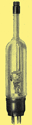
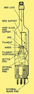
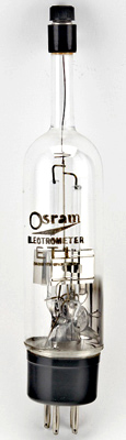
Fig. 1. - The electrometer triode has an extremely high input impedance, and is designed for use as a substitute for electrostatic measuring instruments.
The electrometer triode, illustrated in Fig. 1 and explained here with an example here, was first developed towards the end of 1930, and has proved of value to many workers in laboratories and factories for the accurate measurement of electrostatic potentials and very small electric currents. The chief characteristics of the electrometer today is its extremely high value of grid-cathode impedance. In standard types of triode - as used in radio receivers - the grid-cathode impedance may reach ap value of 109 MΩ but seldom exceeds this value so that such valves could not be employed to replace electrostatic instruments. The electrometer triode was designed with a view to removing this limitation, and in the type illustrated, the insulation resistance between grid and other electrodes is greater than 1017 Ω. It has also been found possible in this valve to reduce the total residual grid current to less than 10-15 A , while retaining reasonable sensitivity. At 1,200 kHzs the input impedance exceeds 100 MΩ.
These features are achieved by mounting the control electrode, or grid, in the form of a flat plate supported from two pillars of special high resistance glass, the grid lead being taken to a terminal through the end of a stem also of high resistance glass, and sealed to the top of the bulb. The anode and filament are mounted on a glass pinch which supports the two pillars. In the glass used for the bulb and stem in the electrometer triode care is taken to ensure low surface leakage, unaffected by exposure to the atmosphere over long periods.
Ensuring Stability
A further precaution is taken to ensure that the getter surface does not spread over the upper portion of the bulb and the grid insulating pillars. Internal and external guard rings are provided, connected to a pin in the base of the valve. The guard rings and getter surface are arranged to be maintained at earth potential, thus obviating the risk of stray charges accumulating on the glass, and ensuring stability of characteristics. The advantages of this valve over the more usual form of electrometer are comparative robustness, low input capacity and greater sensitivity and stability.
The electrometer triode may be used in several ways [★] Warren, GEC Journal, 6-2 (1935) for the measurement of every small charges and currents, such as photoelectric or ionisation currents, or high resistances. Thus, electrostatic potentials of from 0.1 milliVolt to 6 Volts may be directly determined. A practical application is in conjunction with a photoelectric cell for accurate photometry of lamps. To meet such a case a special tube has been developed, combining the electrometer triode and a standard photo-cell with a grid coupling resistance, mounted together in an evacuated glass bulb (Fig. 2).
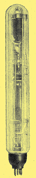
Fig. 2. - For photometry of lamps: an electrometer triode combined with a standard photocell.
Another important application is the measurement of glass electrode potentials in the determination of hydrogen-ion concentration values; also the determination of high resistances and for the study of the piezo-electric effect in crystals.
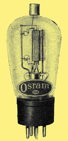
Fig. 3. - A valve voltmeter triode, with high input impedance at radio frequencies
The valve voltmeter triode, as typified in Fig 3, which shows Type A577, is a valve having more or less standard amplifier triode characteristics, but designed to exhibit an extremely high input AC resistance at high frequencies.
The A577 valve consists of an indirectly heated triode system showing a mutual conductance of approximately 2 mA/Volt, but with the grid support wires held by means of two separate glass beads so disposed as to afford a much higher insulation resistance than if the grid were mounted on a pinch in the ordinary way. This construction would render the valve unsuitable for use in amplifiers owing to microphony, but is essential for its particular application for purposes of measurement.
In addition, the grid connection is taken to the end of the bulb remote from the other electrodes. In this type of valve the input AC resistance as measured on a cold valve at 1 MHz is approximately 20 MΩ.
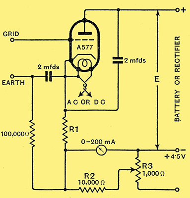
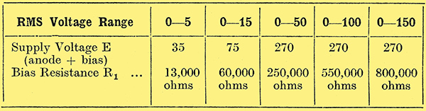
Fig. 4. - A typical valve voltmeter circuit. R1 and R2 constitute the backing-off circuit, with zero adjustment on R3. Suitable operating conditions for various voltage ranges are given in the accompanying table.
The principal application of this valve is in a mains operated or portable valve voltmeter in which the valve operates as an anode bend rectifier and may cover a wide range of voltages when operating at high frequency. A typical circuit diagram illustrates its use as shown in Fig. 4, and such an instrument can be arranged to include the measurement of voltages at all frequencies within the normal radio and audio range.
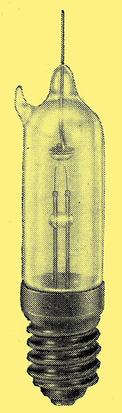
Fig. 5. - A peak voltmeter diode. Type A373.
To meet the laboratory need for a direct reading peak voltmeter to operate on frequencies up to about 100 MHZ/s, the small directly heated diode illustrated in Fig. 5 (Type A373), has been developed. This valve is of small dimensions and operates from a 2.0 Volt filament supply, being capable of use with a peak anode voltage of 2,000 at frequencies up to 50 MHz, or 1,500 Volts at frequencies up to 100 MHz.
The valve employs a short filament system with an anode supported at the remote end of the bulb, the anode connecting wire projecting to carefully defined length beyond the end of the bulb. This valve is so designed that the input capacity is very low (about 0.5 pF.) in spite of a very small anode-filament clearance.
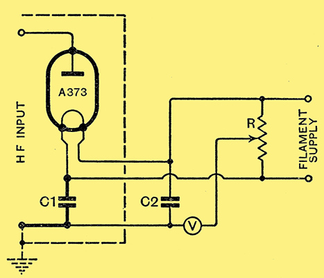
Fig. 6. - Illustrating the use of a special diode for measuring peak voltages. The filament supply must be insulated from earth by at least 500 MΩ. C1, C2, 0.001 μ for any radio frequency; R, 100 Ω, centre tapped; V, electrostatic voltmeter or equivalent.
Fig. 6 illustrates a suitable circuit with Type A373 arranged for high-frequency voltage measurement. For such purposes it is normal to employ an earthed screening case around the RF part of the instrument and an insulation resistance of not less than 500 MΩ between the filament and earth.
Another important application is the measurement of modulation characteristics, for which the diode is used in conjunction with a cathode-ray oscillograph.
With the increasing technical interest in oscillations of ultra-short wavelength, the limitations of the more common triode circuits in producing, amplifying and detecting such oscillations has led to the development of other methods. The principal limitations arise from the inter-electrode capacities and the electrode lead inductances, and also from the transit time of the electrons in their path.
The type of valve which has been developed to reduce the effect of these limitations is known as the split anode Magnetron and a full description of the construction and operation of such valves has been given elsewhere. [★] Megaw, Journal IEE, Vol. 72, p. 326, 1933. Also see extras menu..
The split anode Magnetron is of increasing interest to investigators employing ultra high frequency circuits. This range may be taken as representing wavelengths lying between 10 metres and 1 centimetre, it being estimated that the practical wavelength limit of conventional triodes is about 1.5 metres as an oscillator or amplifier, and rather lower for detection. The split anode Magnetron, illustrated in Fig. 7, which shows type CW10, consists of an emitting cathode contained within an anode divided into two equal segments separated by narrow gaps, each segment being carefully insulated from the other.

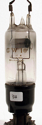
Fig. 7. - Construction of a split anode Magnetron, as used at extremely high frequencies.
The valve operates in a magnetic field with the electrode axis approximately parallel to the lines of force. When under the influence of this field the electrons in their passage to the positive anode experience the deflecting force and, at a certain critical value of anode voltage and field strength, they will cease to reach the anode. This principle is applied in the Magnetron to impart a range of negative resistance to the valve similar in form to the dynatron characteristic arising from secondary emission in a tetrode. If a tuned circuit is connected between the anode segments and the high tension supply, oscillations can be produced and maintained at exceedingly high frequency.
Wavelength and Output.
In the CW10 valve electronic oscillations may also be produced at wavelengths between 22 and 50 cms, and the type is designed to operate normally at an anode voltage up to 1,000 Volts with a dissipation of 50 Watts. The output ranges from 10 Watts at 1.2 metres wavelength to 30 Watts at 3 metres. The possible output increases with both anode voltage and filament emission, provided the magnetic field strength is increased with the anode voltage. For a given anode voltage the behaviour of the circuit can be entirely controlled, apart from wavelength adjustment, by means of the filament and field current rheostats. Using the electronic type of oscillation generator, an output of 2 Watts is obtained at a wavelength of 25 cm.
Other types of split anode Magnetron are:.
Type CW11, which is principally intended for dynatron oscillations at wave-lengths of 1 to 5 metres.
Type E639, which is made with four anode segments allowing alternate wave-length ranges of from 0.5 to 1.5 metre with an output of 20 to 40 Watts, and 1.5 to 5 metres with an output of 20 to 50 Watts.
The field of micro-wave oscillations is one which is largely unexplored and hence the use of the split anode Magnetron is at present restricted to investigation by workers in the fields of both radio communication and medicine. This type of valve may ultimately be employed for pointbto-point working on short-distance radio communication circuits or for radio beacons. The detection of moving objects ('wireless searchlight') is also an important possibility.
Workers in the medical field may discover new and promising possibilities in production of local heating, study of bacteria, etc.
Gas-Filled Types
The development of gas or vapour-filled valves of the hot cathode type for industrial purposes is restricted to diodes for rectification of AC supply, although of recent years the gas-filled relay, which includes a control electrode, or grid, has made its appearance for various applications.
The soft diode may be roughly divided into two groups: first, that which contains an inert gas such as argon, the valves in this group being intended for rectification of currents from 1.0 to 100 Amps at comparatively low voltage; and, secondly, a group normally containing mercury vapour and intended for the rectification of higher voltages.
The principal application of the low-voltage high-current type is to battery-charging apparatus, where it is fairly extensively employed. Mercury vapour filled rectifiers in the form of a thermionic valve, as distinct from the mercury arc rectifying equipments (which are properly included as a branch of heavy electrical engineering), are now available for dealing with a very wide range of working voltages.
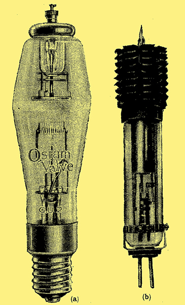
Fig. 8. - (a) A high voltage mercury-vapour rectifier, Type GU2, giving an output up to 2 Amps and (b) a GU8 rectifier, similar to Type GU2, but giving a larger output.
Fig. 8 (a), shows the GU2 type, which is capable of giving an output of 2 Amps at 3,000 Volts in bi-phase half-wave circuit; and Fig. 8 (b) illustrates a similar valve of type GU8. Six valves type GU8 in a three-phase full wave circuit will deliver an output of 20,000 Volts 12 Amps DC.
With all gas-filled, or mercury vapour-filled, valves the current flowing through the valve, while still limited as to its maximum permissible value by the saturation emission of the cathode, is not limited by space charge, and thus anode voltages of 10 to 20 Volts produce the full saturation current of the cathode. A small anode potential (10 - 15 V) will give the electrons emitted from the cathode sufficient energy to provide ions by collision with the atoms of the gas. The conduction of current is thus accompanied by a discharge which appears as a glow in the tube. Owing to the low impedance of the gas-filled valve under conditions of ionisation, the actual current passing through it will depend only upon circuit conditions, and it is therefore important that the external circuit should always contain sufficient resistance to limit the current to the manufacturers rating of the valve.
A further extremely important characteristic of the mercury vapour valve is the necessity for the cathode to be heated to its normal emitting temperature before any anode current is allowed to pass. This, however, is not likely to prove such a big disadvantage in large types used for industrial purposes than perhaps is the case with the smaller types subjected to more frequent switching on and off.
ln mercury vapour-filled valves, particularly where used in high voltage circuits, it is usually important to maintain the ambient temperature between certain limits, and with large valves it is common practice for the temperature of the surrounding air to be thermostatically controlled. Not only must the ambient air temperature be kept below the maximum value permitted, but these valves are very human in their reaction to draughts, which are likely to prove fatal by causing condensation of the mercury above the anode, or by lowering the temperature to a dangerous level.
In addition to the advantage of increased current-carrying capacity by the use of a low pressure of gas instead of a vacuum, there is the possibility of using various devices to increase the efficiency of the cathode which are not feasible in the high vacuum rectifier. Such, for instance, is an improved cathode known as a 'heat-shielded' cathode, which allows the introduction of indirect heating and almost totally encloses the electron emitting surfaces, with less risk of contamination of other parts of the valve with particles of loosened emissive coating. An illustration of an indirectly heated heat-shielded cathode is given in Fig. 9.
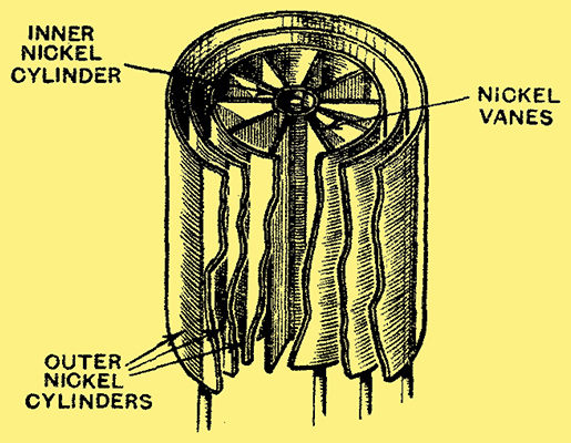
Fig. 9. - An indirectly heated heat-shielded cathode; the outermost cylinders act entirely as heat shields.
The cathode consists of a number of vanes of thin nickel mounted radially on a nickel cylinder, these being surrounded by an outer nickel cylinder. The spaces enclosed between the vanes are coated with the emitting material, and the whole is heated internally by a tungsten heater mounted inside the inner cylinder. Heat-shielded cathodes of this type can be made to give very high emission efficiencies, even up to about 3 Amps peak emission per Watt, which compares with 0.1 Amp peak per Watt for a simple straight oxide coated filament.
The importance of observing the cathode pre-heating time is increased with such a cathode, and, with a cathode rated at 100 Watts, this may be of the order of fifteen minutes.
The development of gas-filled relays has received a good deal of attention both in America and in this country, and the applications of this device in industry are possibly only just being appreciated by electrical engineers. The principle of the gas-filled relay has already been-described here and consists of the introduction of a control electrode (which might be called the grid) into an inert gas or mercury-vapour filled rectifier, the introduction of this electrode serving to prevent the discharge, so long as the voltage applied to the grid is kept more negative than a certain value dependent on the anode voltage.
Typical gas filled relays developed in this country commercially cover a range of anode current from 1.0 Amp peak to 25 Amps peak, or from 0.3 Amp average value to 8.0 Amps.
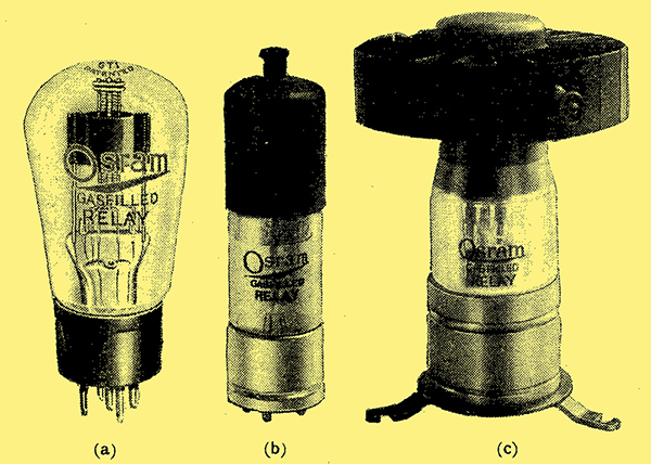
Fig. 10. - Typical gas-filled relays: (a) Type GT1, (b) Type GT5E, (c) GT25E.
Illustrations of gas-filled relays included in this range are given in Fig. 10 (a) GT1, (b) GT5E & (c) GT25E.
The GT1 (The later GT1C was used in the Colossus machine) is designed with an indirectly heated cathode containing a heater of 5.2 Watts, and will withstand an anode voltage of 1,000 peak with an RMS value of anode current up to 0.5 Amp. The GT5E has an indirectly heated cathode with an air-cooled anode, and is fitted with a heater rated at 20 Watts. This tube is capable of withstanding an anode voltage of 1,000 Watts peak, with a maximum current of 2.5 Amps RMS.
A 12 Amp Output
The GT25E is a larger tube, also employing the air cooled anode but designed with a heat-shielded cathode as previously described. The heater in this relay is rated at 40 Watts, and a maximum anode current of the order of 12.5 Amps RMS for an anode voltage of 1,500 peak. The simplest application of the gas-filled relay is as a trigger device, where a small variation of grid voltage is used to cause the starting of a steady anode current. So used the relay will provide a permanent indication of a single transient effect of any kind which can be converted into a voltage variation, however short in duration. The anode current may be made to perform various functions, such as working an alarm, starting up a motor or operating a relay, or, for instance, it may be used in conjunction with a contactor to open a circuit in the event of an overload occurring in that circuit.
With DC applied to the anode it is necessary to reset the relay each time it is operated by removing the anode voltage momentarily and thus allowing the grid to regain control.
A common application of the relay as a simple trigger device is in conjunction with the photo-electric cell, together with an electro-magnetic relay, so that the gas-filled relay is made to break its own anode circuit after each discharge. This method is applicable to counting mechanisms, and, as such, is employed to some extent by industrial concerns.
As it is capable of carrying large currents without excessive internal dissipation, the relay is able to perform the function of a contactor, switching on heavy currents under the control of a small grid voltage change. The power necessary to control a current of several Amperes may be only a few milliwatts.
In an inverter to change DC to AC voltage, two gas-filled relays are normally employed; the method has been adequately described elsewhere. The inverter can be made self-excited, and then provides a convenient source of AC supply (not necessarily of sinusoidal wave form) of any voltage or Wattage, dependent upon the size of relays employed, from a DC source without the introduction of any mechanical moving parts. The employment of gas-filled relays in inverter circuits should enable efficiencies of 90% or over to be realised with high-voltage DC supplies. Special precautions in the design of the inverter circuit are necessary in order to deal with loads of poor power factor and to make the circuit proof against accidental short-circuits.
By the application of an AC voltage to the anode the relay is automatically self-resetting during each cycle of the anode supply voltage, and in this case, by means of a variable applied grid bias, the average anode current can be controlled continuously from zero to that corresponding to current flowing during the whole half-cycle in which the anode voltage wave is positive. With an AC voltage applied also to the grid, the flow of anode current can be controlled by the phase relationship between the anode and grid voltages, the average rectified current passing through the tube changing from zero to its maximum value.
Typical applications of this may be found in furnace temperature control, DC motor speed control, or voltage control of a generator by variation of field excitation.
A further application which may have a promising future is that of dimming lighting circuits, in which the amount of light given by an installation may be varied from zero to full brilliance remotely controlled by means of a small potentiometer. Very beautiful effects may be obtained in this way by combining and changing the value of illumination given by a number of lamps of different colours, such as in stage lighting, etc.
The capabilities of the gas-tilled relay have already been successfully demonstrated, and there is little doubt that it will ultimately take its place with other devices as a standard piece of electrical equipment.
Mention has not been made here of the application of standard amplifying triodes, etc., to industrial use, though these are becoming increasingly employed, particularly for public address work, and as electrical 'call-boys' in hotels etc.
The scope of thermionic valves applied in one form or other to traffic control is unlimited, and such experiments as have already been conducted on these lines indicate the possibilities in this direction.