The 20P4 is purpose designed as a television line output valve.
In September 1953 Mazda described the 20P4 as having a redesigned g2 with consequent reduction in screen dissipation and increase in power handling on positive pulses. The sensitivity of the valve has also been increased. This exhibit looks like an early version.
The valve can withstand a positive anode surge of 6 kV. The screen grid can dissipate 5 Watts. The originally white lettering has darkened through many hours of operation.
All the electrodes can be seen in this image. The outer anode has the bright beam plates within then the central column has the two wire grids that share the same pitch and in the centre is the cathode.
The rectangular cathode tube has the heater pass through it four times. The anode has side flanges at the point of greatest heat generation to add extra radiating surface. The control grid supports are made of copper for good heat transference.
A closer view below the lower mica.
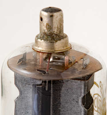
The top mica showing the wide cathode and connection between anode and top cap.
The wide glass tube envelope is 29 mm in diameter and, excluding the IO base pins, is 91 mm tall.
References: Data-sheet & 1040. Type 20P4 was first introduced in 1953. See also1953 adverts.