|
PFL200Sensibly equivalent¶ to:16Y9See also:
|
|
|

|
The PFL200 combines a screened amplifier pentode and an output pentode in the one envelope. It was designed for television use as video amplifier and video output. The mutual conductance of the output pentode at 21 is very high, pointing to a very small space between cathode and control grid.The valve was used for video output in colour television receivers. Three would be used per receiver, one per gun. The second pentode would be used in the colour difference circuitry. The presence of the internal screen points to the video usage.When used in monochrome receivers the valve was used for video output and the low power pentode as a sync pulse separator.The B10B base was a late introduction, near the end of the use of valves in consumer products. By putting two pentodes in a single envelope the price would have been lower for set manufacturers in overall assembly costs.The stylised M logo dates the valve to 1970 or later.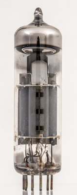
The gaps in the power section anode show the beam tetrode construction and the edge of the screen grid support.
The amplifier pentode on the right can be seen to have three wire grids. The middle hole reveals the control grid passing flat across the cathode (left side) with the other two grids less flattened as they pass across the caathode.The thin glass tube envelope is 20 mm in diameter and, excluding the B10B base pins, is 70 mm tall.References: Data-sheet & 1040. Type PFL200 was first introduced in 1964. See also 1964 adverts. |
Pin Connections
| 1 | 2 | 3 | 4 | 5 | 6 | 7 | 8 | 9 | 10 |  g1(2) | k(2),g3(2) | g2(2) | a(2) | h | h | k(1),g3(1),s | g1(1) | g2(1) | a(1) |
|
|
Absolute Maximum Operating Conditions
| Vh | Ah | Va | Vs | Vg | mAa | mAs | ra | gm | 
| 16.5 | 0.3 | 150 | 150 | -2.3 | 10.0 | 3.0 | 0.16M | 8.5 |
|
Absolute Maximum Operating Conditions
| Va | Vs | Vg | mAa | mAs | ra | gm |
| 170 | 170 | -2.6 | 30.0 | 6.5 | 40,000 | 21.0 |
|
Updated June 08, 2025.
|
|