The PCF200 was designed for use in multiple stages of a television receiver.
This exhibit has the later logo that was introduced in 1970. The earlier pejorative term 'Foreign' has been replaced with the neutral term 'Imported' as protectionism declined.
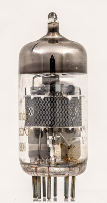
The screen hides most of the structure. This image is looking at the triode. The heater is coiled, the cathode is flat faced.
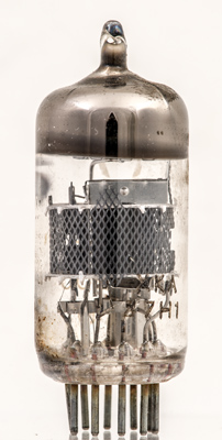
The triode on the left with the pentode on the right. The pentode anode is pressed into two active plates and a joining strap.
The thin glass tube envelope is 20 mm in diameter and, excluding the B10B base pins, is 48 mm tall.
Reference: Data-sheet. Type PCF200 was first introduced in 1964. See also1964 adverts.