|
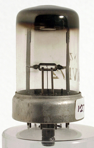
The CV172 noise diode was developed to provide a standard noise source for the testing of radar IF amplifiers. The fundamental parameter in an amplifier's performance is called the noise figure. This is a dimensionless quantity and a low figure indicates the ability to resolve weak signals. Background noise decreases with increasing frequency (mainly true) and so the performance of the receiver is the limiting factor. Early radar used point contact crystal detectors to convert the reflected microwave signal into an IF of about 45 MHz. During the early 1940's 45 MHz was as high a frequency as high gain wideband amplifiers could operate. The Mullard EF50 being the first effective valve at these frequencies.
Diodes used as noise generators should have the following characteristics: pure tungsten or thoriated-tungsten filament, good saturation (the reciprocal of the slope of the anode-current vs anode-voltage curve should be at least fifty times the required generator resistance), short leads and low capacity. Also, for matched-line use, diode noise generators should have a moderately-large emission and anode dissipation.
The basic noise figure test setup is to feed a noise generator into the test amplifier and to take the output from the amplifier to a power indicating device via an attenuator.
The noise generator can be replaced by a short circuit of the test amp input. The attenuator is fixed (ie. not adjustable) and can be replaced by a direct bypass. The noise generator output level is adjustable by controlling the DC current through the noise diode, and is calibrated. The 'power indicator' may be a special-purpose well-shielded RF amp + detector feeding a level meter, but in any event need not be calibrated.
Initially the test amp input is shorted and the attenuator bypassed. The power indicator consequently shows the noise output of the test amp and its level is noted. Both the noise generator and the attenuator are then switched-in, and the noise generator output adjusted so as to obtain the same output level indication as before.
The effective input noise power Wn of the amplifier can then be calculated from the noise generator output power Wg from this equivalence:
A.Wn = A.(Wn + Wg)/a
where 'A' is the amplifier gain and 'a' the attenuation factor.
Simplifying and rearranging,
Wn = Wg/(a-1)
So (for example)
a= 2 (attenuator output = 1/2 input) -> Wn= Wg [the usual case]
a= 3 (attenuator output = 1/3 input) -> Wn= Wg/2 etc. Since Wg is accurately known, the rest follows directly.
|