|
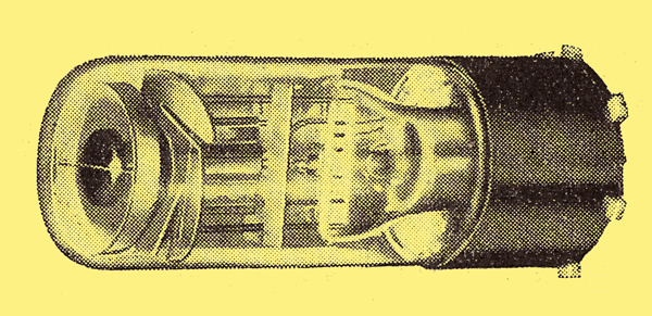
The TV4 illustration from the original.
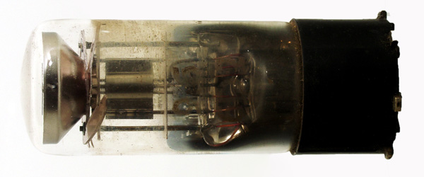
The TV4 exhibit.
Various types of tuning indicator have been produced from time to time, but the meter and the Neon, indicators have so far held the field. A new indicator has now arrived to challenge their supremacy: this is the Mullard TV4, and it operates upon the cathode-ray principle. It comprises a miniature cathode-ray tube with a triode amplifier built into a single glass envelope; in external appearance it is rather like a valve of, unusually small dimensions, and the lower part carries the triode elements. The upper part contains the cathode-ray tube, however, and the indications are seen through the top of the bulb, which must consequently be mounted in a visible position.
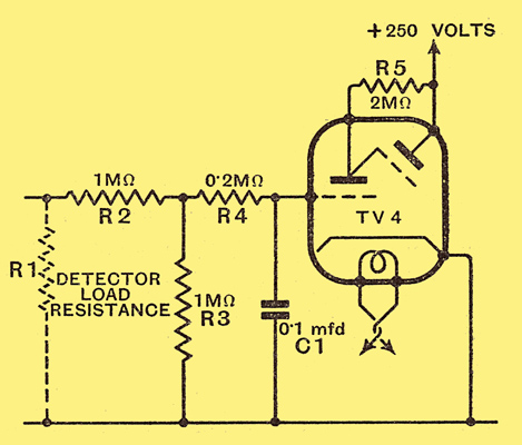
The recommended circuit for the new tuning indicator. R1 is the load resistance of the diode detector.
The circuit connections recommended by the makers (Mullard) are shown above, and it will be seen that, the input to the triode amplifier is derived from the load resistance R1 of the diode detector through a resistance-capacity network comprising R7, R3, R4 and C1. The purpose of R2 and R3 is chiefly to keep the loading on the detector at a minimum while permitting R4 C1 to give good filtering, so that the indicator is not influenced by the modulation on a signal. Maximum indication is secured with only 4 Volts input to the triode. The triode-anode is joined to the target of the cathode-ray tube through a 2-megohm resistance: R5; and the latter electrode is connected directly to the HT supply which must be not more than 250 Volts.
The valve is indirectly heated and consumes 0.3 ampere at 4 Volts, and the heater takes 20 seconds to warm up. Under normal operating conditions with no signal, the triode anode current is 120 μA and the target current 0.29 mA. With a signal giving an input of -4 Volts to the triode, and hence full indication, the currents fall to 30 μA and 0.7 mA respectively.
The makers set certain limits, and it is recommended that the resistance in the grid circuit of the triode should not exceed 2.5 megohms, and that the voltage between heater and cathode should not be greater than 50 Volts. Furthermore the target voltage must never be more than 250 Volts, and the tube should be operated under such conditions that full indication is always obtained on a signal.
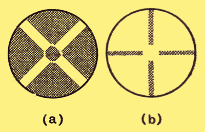
When no signal is tuned in the indicator shows a green cross on a dark ground (a) but when a signal appears the illumination spreads and the effect is that of a dark cross on a green ground (b).
When the receiver is tuned to no-signal a narrow cross of green light appears at the end of the tube, as shown above at (a). This broadens on tuning in a signal and at first assumes rather the shape of a Maltese cross; eventually, when full indication is secured, almost the whole of the tube is light save for a narrow cross of dark as shown at (b). Actually there are four sets of light, and the width of the segments increases with signal strength until the limit of indication is reached and practically the whole area is illumined.
The tube, must: be correctly mounted if even illumination is to be secured, but this is readily arranged by rotating the base correctly. The indicator is fitted with a side contact base, the connections for which are given below.
On test the indicator functioned in a very satisfactory manner and gave a clear-cut ie It proved to be rapid in action and to be unaffected by the modulation of a signal. The appearance is good, and is certainly assists in making the tuning of a receiver easier for the unskilled. The component is priced at 17s. 6d.
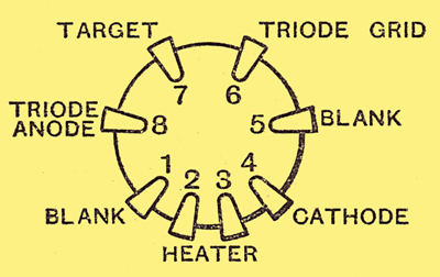
The Ct8 base connections of the TV4 indicator.
|