|

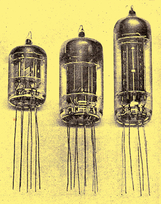
Examples of flying lead valves suitable for direct wiring-in and clamping by the user
In the past the valve as a component has taken the blame for 50% of all equipment failures-if it is fair to blame something for failing to stand up to conditions for which it was not designed. The Special Quality valve, however, has been designed to work under arduous conditions, and with such valves the basic reliability of this component has improved vastly. With this position established, and an assurance that if valves are used correctly and conservatively there will be a very low failure rate up to the normal length of life, then there is a good case for wiring-in valves in the same manner as other circuit components.
The major difficulty here is that of custom, and it is hard to change the mentality of the servicing technician whose first approach to the diagnosis of an unusable equipment is to pull out the valves. This tendency is overcome by making this instinctive action not possible and results in many advantages. Some 30-50% of the valves so removed are perfectly satisfactory when tested, whilst many modem equipments are so compact that the removal of valves often results in mechanical damage to them. Then again, the use of soldered-in valves highlights the importance of giving the earliest consideration to methods of fault diagnosis and makes it necessary for the equipment designer to supply detailed procedures that will enable the real faulty component to be removed-this will improve the 'unreliability record' of the valve to a surprising extent!
At the same time, it will give emphasis to the value of marginal checking techniques. Valves must die eventually of general deterioration of characteristics, but by routine diagnosis of the equipment performance it is possible to forecast potential failures and thereby increase equipment reliability by a whole order or more.
Next, by making valves with flexible leads instead of pins the valve manufacturer is able to produce a stronger glass article, and because there is no mechanical incompatibility between the valve pin spacings and the valveholder contacts there is no risk of strains being set up that will result in broken and leaky valves in service.
Finally, by dispensing with the conventional valveholder it is easier to provide satisfactory intimate metallic contact to the glass envelope and thus achieve greater cooling. The question of bulb temperature is now being studied extensively, and it is established that the life of a valve is very dependent on this temperature. Reducing it by 50-60°C can increase the life in many cases by four or five times. By using black metallic clamps specially designed to touch the bulb at as many places as possible the hot spots are evened out over the bulb surface, and then by secure fastening of the clamps to the chassis the heat is conducted away efficiently.
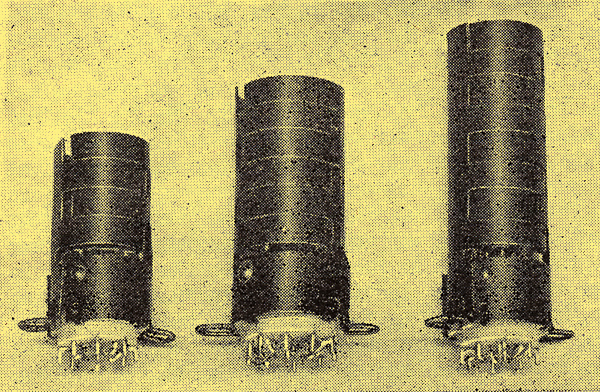
Many users purchase flying-lead valves in the form shown in Fig. 1 and design their own clamps to fasten the valves horizontally on the chassis. The ordinary U-shaped saddle, with the metal band situated at the hot spot of the glass envelope, is one of the simplest methods. Other users prefer to maintain their present circuit techniques and mount the valve in the usual vertical position. To suit such requirements a range of Special Quality valves is available in which the user is supplied with a 'valve component' as shown below. This is a flexible-lead valve with its own cooling shield and with soldering tags in the conventional pin positions. The can has two lugs with normal hole fixings and thus the 'valve component' replaces the usual arrangement of valveholder, valve and shielding can or springs.
The time has now arrived when the adoption of such wired-in valves, used conservatively and correctly with approved maintenance and marginal checking procedures, will produce equipment reliabilities very much in excess of those at present being achieved.

Flying-lead valves already mounted in cooling cans and connected to soldering tags corresponding to conventional valveholders.
|