|
A Stabilised Power Supply Unit
Articles on power supply units have appeared from time to time in the wireless press, most of them providing for a wide range of outputs with extensive means of control and metering, and calculated to satisfy even the most unorthodox requirements in the experimenters workshop. The power unit to be described, however, provides only a series of fixed but constant outputs at voltages usual in mains equipment.
Basic Stabilovolt Circuit
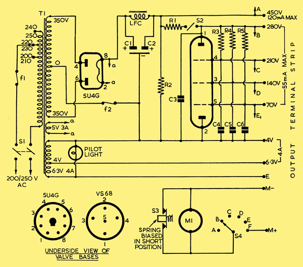
Various designs were considered, but the final circuit, shown below, has proved to be the most economical, reliable and compact. Heater current is obtained in the usual way, while a 5U4G full-wave rectifier and normal smoothing circuit provides the main HT of about 450 Volts when the components specified are used. To obtain HT supplies other than the above, however, an ex-WD Stabilovolt type VS68 (Marconi Wireless Telegraph Co. STV280/40) was used. The completed unit therefore provides heater current at 6 and 4 Volts, and high tension current at 450, 280, 210, 140 and 70 Volts. The latter four outputs remain constant up to loads of 55mA.
Complete Circuit
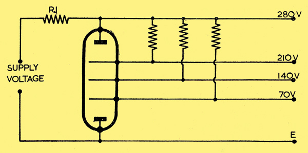
The stabilovolt requires an ignition voltage greater than its normal working voltage; actually resistor R1 controls the ignition, since until the tube is operating very little current is drawn and consequently very little voltage drop occurs. Once the tube is operating, R1 prevents the tube from passing current above its rated maximum of 60 mA. Resistor R1 equals:-
1000 (supply voltage max, tube operating voltage)/(tube operating current in mA) Ω
The final choice of 3kΩ is a convenient value and allows a slight safety margin. It should be noted that the current through R1 will not fall below the operating current of the tube. Switch S2 puts the stabiliser out of circuit when it is desired to use the full HT at 120mA.
Resistors R2, R3 and R4 specified at 250kΩ 0.5 Watt aid ignition of the VS68 while capacitors C3, C4, C5 and C6 bypass noise generated by the tube.
The metering circuit controlled by switch S4 is a luxury and enables an output to be selected and the current readily measured. Unless a multi-range meter is used, meter M1 should have a maximum reading of 200mA. Switch S3, biased in the 'short' position, shunts the meter until a reading is actually made. The meter may be used separately via terminals M- and M+.
Two fuses are installed; fuse f1 rated at 1A in the input circuit protects the mains, and gives a degree of protection to the transformer should the heater winding be inadvertently shorted; fuse f2 rated at 200mA protects the HT circuit.
The actual layout is not important, but should be so arranged that wiring is kept short and those components which dissipate heat, in particular the 5U4G, VS68 and resistor R1, are given plenty of ventilation.
On completion the wiring should be carefully checked to ensure that no error has been made; examine the fuses, also.
An easy yet effective way to test the complete unit is as follows:-
Connect a 10kΩ resistor between terminals M- and E; a 20 Watts rating would do, but a smaller rating could be used if a burnt up resistor is no objection.
Switch on and allow time for warming up of 5U4G.
Meter M1 should indicate the following readings at given position of switch S4, A-45mA; B-28mA; C-21mA; D-14mA; E-7mA; F-no reading.
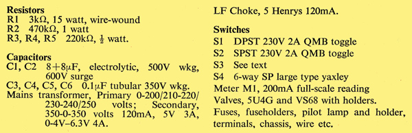
List of Components
|