|
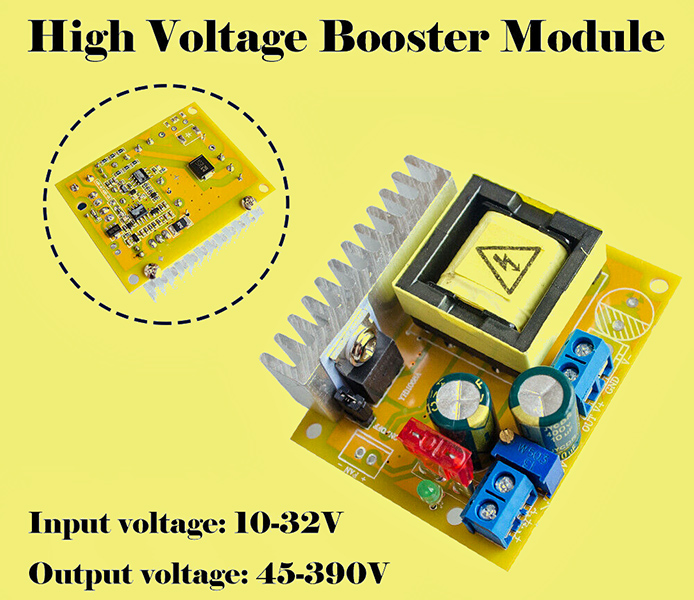
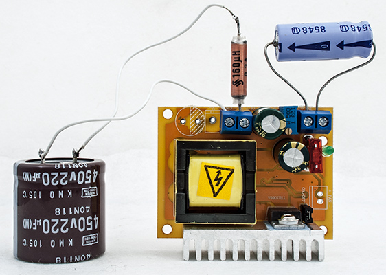
An example of the DC-DC converter used by the author.
Conventional valve HT supplies are a mainstay of the modern audio amplifier but AC within the chassis introduces hum and for an experimenter the presence of mains AC within the equipment is a constant hazard. Switch mode power supplies have replaced 50/60 Hz mains transformers in most devices and in particular the supplies for laptop computers are readily available with power outputs of around 20 Volts at 4 Amps. To use these in projects keeps the lethal AC mains away from live equipment. What is needed for valve work is a suitable DC-DC converter for the HT. Step-down converters, current limited, to feed heaters are readily available. By limiting the in-rush current the valve's lives are not shortened.
The author used DC-DC converters in the build of an open board pair of mono-bloc amplifiers in 2016. The HT converter being 10 W and designed for audio - but not cheap. For projects with a DC input of 10 W and greater a new solution was required.
The DC-DC HT converter pictured at the top of the page is available from ebay suppliers at reasonable cost and is quite suitable for a constant output of 25-30 Watts. HT voltages up to 390 Volts can be had. At high voltages the current is, of course, reduced and around 50 mA should be seen as the safe maximum. For 250 Volts a current of 100 mA is a respectable supply.
The catch is that these DC-DC converters are electrically noisy and require significant peak currents from the supply. Even a three amp supply has the current limiter triggered repeatedly. It is also surprising that when powering an amplifier there is hum of a few hundred Hz on the audio, given the switching frequency is over 100 kHz.
The author had a set of 160 μH 0.3 A inductors from an old switch mode power supply. One was inserted between the DC-DC converter and the 220 μF output capacitor, just to see what the effect would be. It seemed that the inductor was the correct size. But time to investigate.
Initially a 1,000 μF capacitor was placed across the input and the load, a 25 Watt light bulb, connected directly across the output. The lamp lit correctly but a buzzing could be heard from the board. At 19.5 Volts input the drawn current was 1.56 Amps.
The second set-up is an input capacitor of 1,000 μF and an output capacitor of 220 μF. A 25 Watt 240 Volt bulb was again the test load. To investigate the input spikes a 0.22 Ω resistor was placed in series with the 19.5 Volt supply. For testing a linear bench power supply was used. The current drawn was around 1.6 Amps but kept fluctuating.
The third set-up included the 160 μH inductor feeding the output capacitor. The input current was a stable 1.46 Amps, lower than indicated with the lamp alone. This suggests an improved conversion efficiency.
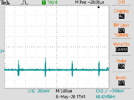
Input spikes when supplying 25 Watts.
From the trace the spike can be seen to be just under 3 Amps on a average current of 1.46 Amps. The spike activates the current limiter - set at 3 Amps.
The output trace had a similar set of spikes. With a resistive load there was no sign of the audible frequency.
On-line are many articles on the noise reduction techniques for DC-DC converters mainly written for high current, low voltage devices. In general an inductor is used to reduce the current spikes that charge the output capacitor. Much the same as would be used for 50/60 Hz HT supplies.
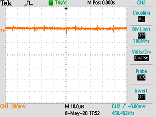
The output with 160 μH inductor.
The output noise reduced considerably and the input stopped running into the current trip on the power supply. It is possible that the switching circuit was charging the output capacitor only when the voltage difference reached a set value and that the inductor spread the charging over several cycles and thus reduced the peak.
Looking at the output spike in more detail it can be seen that the inductor is ringing.
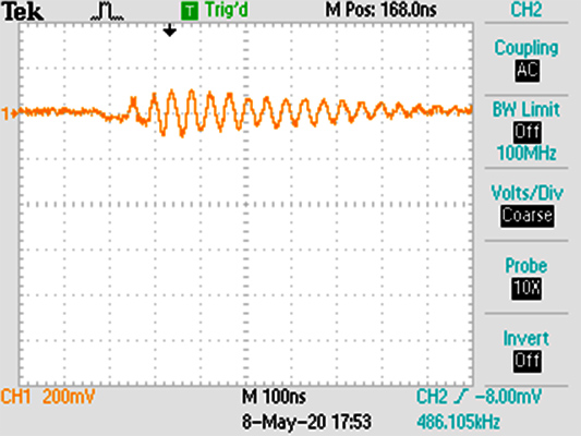
The ringing waveform from the inductor measured across the output capacitor.
The ringing is at high frequency and 200 mV pk-pk on the 240 Volt output.
Electrolytic capacitors do not pass high frequencies and so a low value capacitor was installed in parallel with the 220 μF capacitor. No difference was observed.
The HT supply was used to power the amplifier in the Simplex Stereo experiments as well as the 2E26 prototype. In both cases the output from the amplifier was unchanged from the results obtained from the Heathkit stabilised HT power unit.
The test set-up.
A note of caution: having the wrong values of L and C can upset the internal circuitry. With a 25 W load, 160 μH inductor and a 220 μF capacitor the current drain at 19.5 Volts was 1.46 Amps constant. However, with a 47 μF capacitor the current drain kept increasing to over 1.8 Amps. None of the top components were getting warm but on the underside of the board the output diode had heated so much that it melted the plastic desk protector.
The 1,000 μF 25 V capacitor across the input was originally present to provide anchor points for the 'croc' clips from the power supply. It also adds to the on-board input reservoir capacitance.
|