|
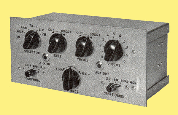
Prototype of stereo pre-amplifier
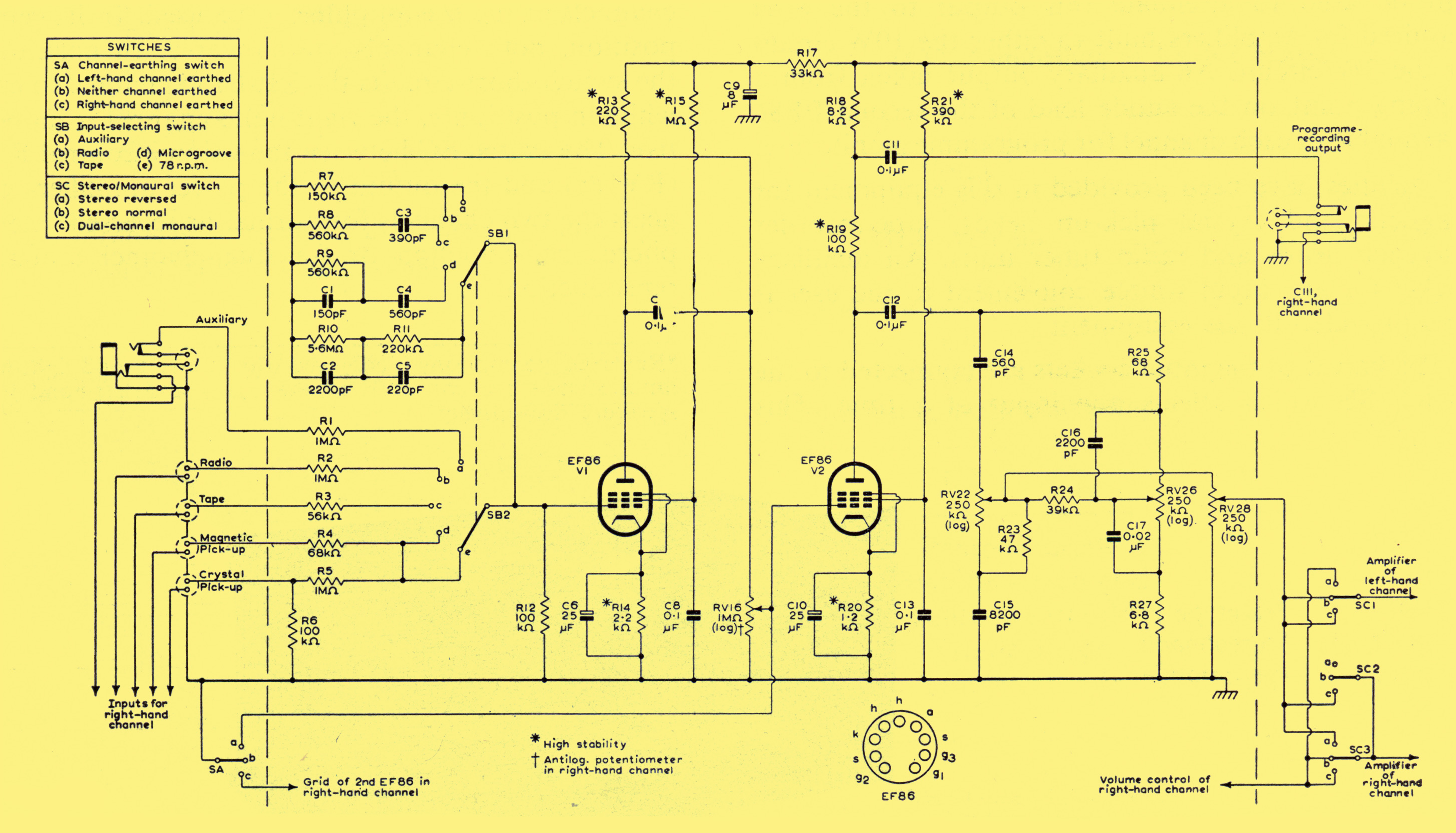
The circuit diagram for a high-quality dual-channel stereophonic pre-amplifier is drawn below. Only one channel is shown in the figure. The circuitry which appears between the dotted lines is for the left-hand channel and it should be duplicated for the right-hand channel. The switches and sockets which are drawn outside the dotted lines are common to both channels.
Circuit diagram of stereo pre-amplifier (left-hand channel only is shown: circuitry between vertical dotted lines should be repeated in right-hand channel)
The circuit is fundamentally a combination of two two-valve pre-amplifiers, so that the total complement of valves is four low-noise pentodes, type EF86. Each channel is arranged to give an output voltage high enough to drive an amplifier built to the 10 W design.
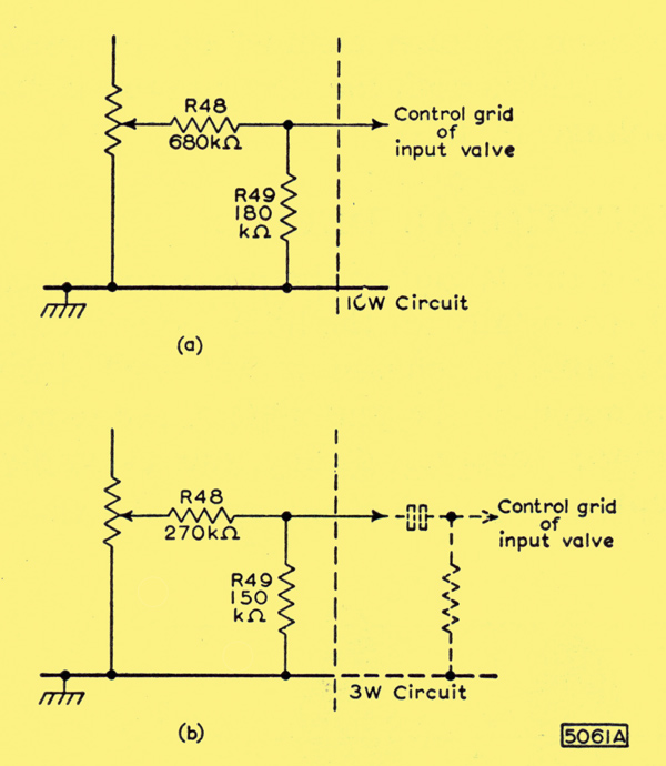
Output-attenuating network
A simple potential divider can be used to attenuate this output to the level required for amplifiers built to either the 10 W circuit or the 3 W circuit. An auxiliary output taken from a tapping point on the anode load of the second EF86 is available in each channel for programme monitoring.
Facilities have been provided in this equipment for magnetic and crystal pick-up heads, tape-recorder playback heads and radio tuner units. An auxiliary socket for any input source convenient to the user is also provided in the equipment.
The halves of the input sockets are connected to the switch SB which selects one input at a time. This switch also short-circuits the unused sockets to earth, an arrangement which reduces considerably the amount of 'break-through' between inputs. The positions of the switch, from left to right, are: Auxiliary, Radio, Tape, Microgroove and 78 rpm.
The equalisation for disc recordings conforms to the present (1950s) RIAA characteristics which have been adopted by most major recording companies. The tape playback characteristic is intended for use with high-impedance heads when replaying pre-recorded tapes at a speed of 7.5 inches per second. The tone controls used in each channel cover a wide range of frequency and provide boost and cut for high and low frequencies. The switch SA permits either or both channels of the pre-amplifier to be used. In its central position, both channels are available. In position (a), the switch short-circuits the left-hand channel to earth while in position (c), the right-hand channel is inoperative. The switch SC between the volume control RV28 (RV128) and the output to the power amplifiers connects the two channels for normal or reversed stereo-phonic reproduction or for dual-channel monaural reproduction. Note: Reversed stereophony is achieved when the left- and right-hand input signals are conveyed to the right- and left-hand loud-speakers respectively.
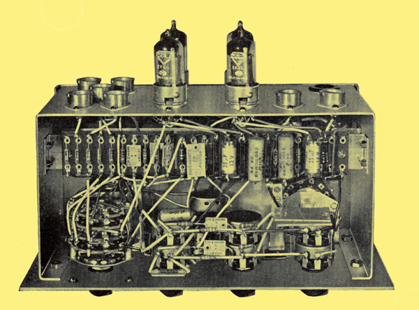
Top view of prototype pre-amplifier
Circuit Description
Each channel of the pre-amplifier is made up of two stages, and each stage uses a Mullard high-gain pentode, type EF86. All the equalisation takes place in the first stage, and is achieved by means of frequency-selective feedback between the anode and the grid of the first EF86. There is no feedback in the second stage, and the output from the anode of the second EF86 is taken by way of the capacitor C12 to a passive tone-control network.
This arrangement has been chosen because the grid-circuit impedance of the first stage should be low. A low impedance at this grid lessens hum pick-up and reduces the effect of plugging-in external low-impedance circuits. Furthermore, the arrangement also results in low gain in the first stage. Hence, Miller effect between the anode and grid of the first EF86, which can be troublesome when high values of resistance are used in series with the grid, is reduced. Series resistors are used in the input circuit so that the sensitivity and impedance of any input can be adjusted accurately. The component values given are intended for sources encountered most frequently, but the sensitivity and impedance for each input can be altered by changing the value of the appropriate series resistor. Note: The impedance at each input includes the grid impedance of the EF86 modified by the feedback components as well as by the impedance of the input network.
Maximum output is obtainable with the arrangement shown above, and the output voltage developed is sufficient to drive the 20 W circuit described in 5-20 Amplifier. This output voltage can be attenuated to the level required to drive the 5-10 Amplifier 10 W or 3-3 Amplifier 3 W circuits by introducing the appropriate network shown below between the volume control RV28 and the switch SC in the main circuit diagram. An auxiliary output signal, which is suitable for monitoring programmes, is taken from a point on the anode load of the second EF86.
To compensate for any differences in acoustical output that may occur in the two amplifying channels, a balance control consisting of RV16 and RV116 is included between the two stages. This consists of a logarithmic potentiometer connected in reverse in one channel ganged to an anti-logarithmic potentiometer connected normally in the other channel. The characteristics of such a control are discussed here.
Dual-ganged potentiometers are used in the prototype for the tone and volume controls. It may be found more convenient to use dual-concentric potentiometers which allow separate adjustments to be made to the channels. If this type is used for the volume control RV28, RV128, there will be no need for the balance control RV16, RV116, which can thus be replaced by fixed resistors (1 MΩ).
The DC supply of the power amplifiers can be used to provide the HT supply for the channels of the pre-amplifier. The smoothing components should normally be mounted in the chassis of the power amplifier used with each channel. The values of these components will vary with the type of power amplifier used, and suitable values are indicated in Table 1. The HT current drawn by each channel of the pre-amplifier is 3 mA at 230 V, and the LT current is 0.4 A at a heater voltage of 6.3 V.
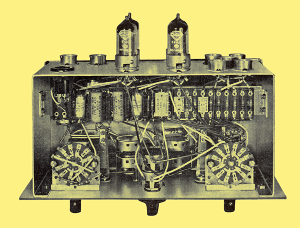
Underside view of prototype pre-amplifier
Construction
The chassis and layout of the pre-amplifier have been designed specifically for the home constructor. A conventional box-type chassis is not used. Instead, the chassis is made on the unit system, the separate parts being joined together during the assembly of the equipment.
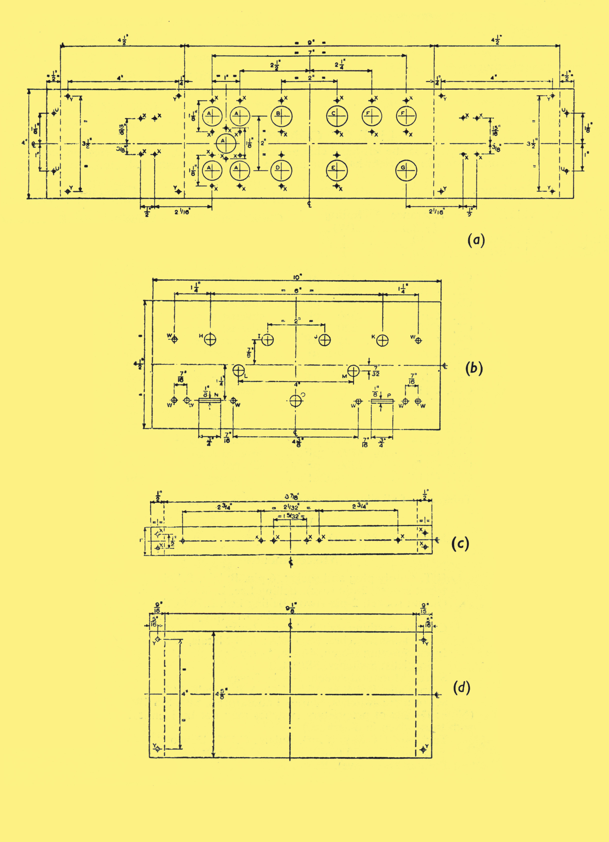
The chassis is made up of six separate pieces of 16 SWG aluminium sheet, the dimensions (in inches) of which are as follows:–
(a) Rear panel 19 x 4
(b) Front panel 10x41
(c) Mounting strip (two) 9.875 x 1
(d) Cover plate (two) 10.25 x 4.625
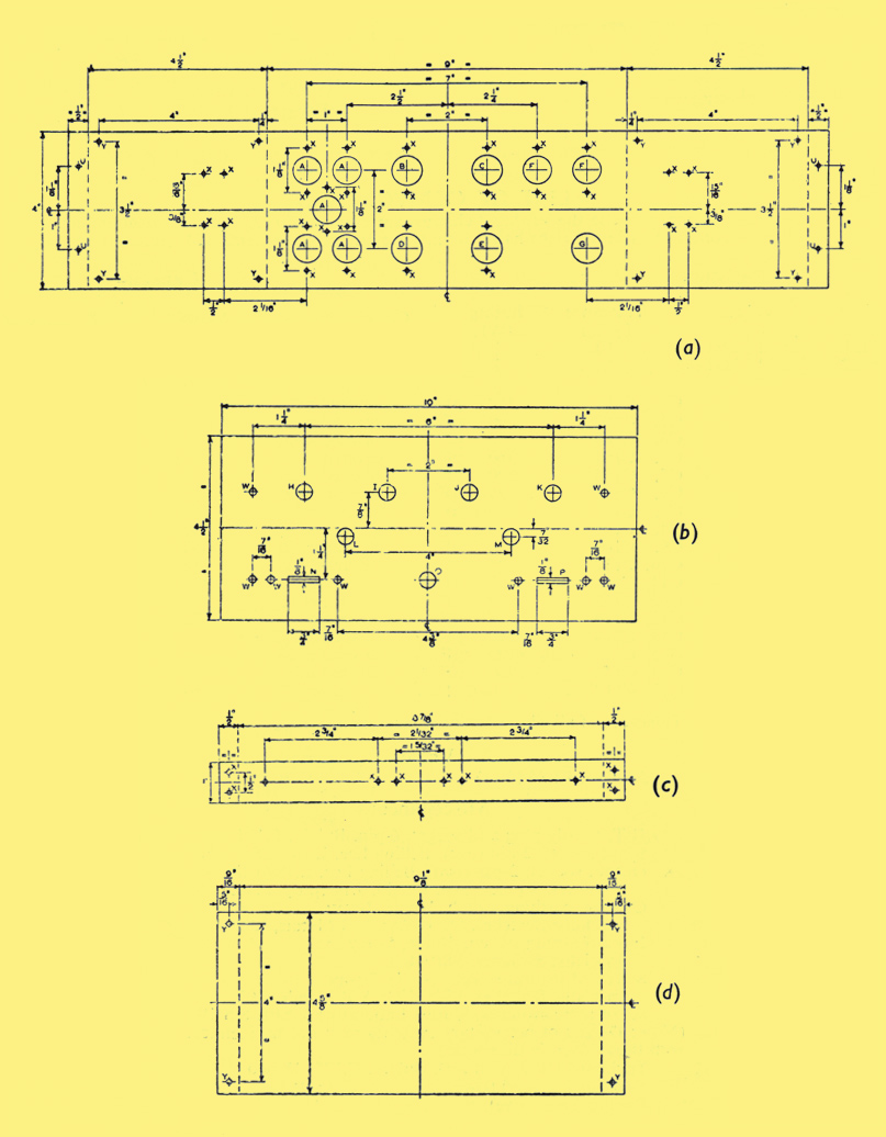
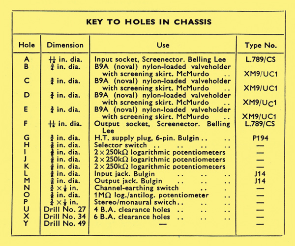
Chassis details
Each piece should be marked as shown above and the holes should be cut as indicated. It is important that, when bending the pieces, the scribed lines should lie exactly along the angles. This ensures that the pieces will fit together properly when assembled.
For ease of assembly, components should be mounted on tag-boards, and these should then be bolted to the mounting strips before the strips are attached to the rear plate. Diagrams showing the positions of the components on the tag-boards are given below.
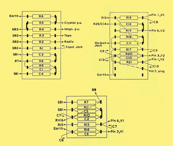
tag-board One (left), Two (lower centre) and Three (right)
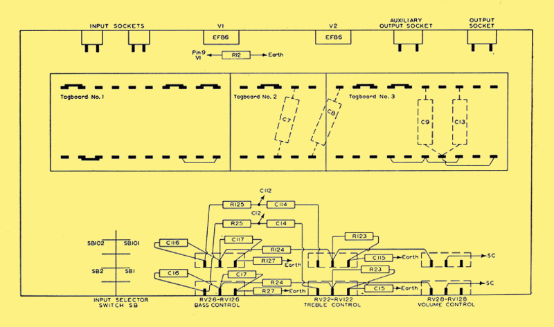
Suggested layout of components - top view
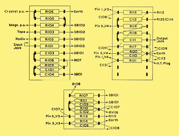
tag-board Four (left), Five (lower centre) and Six (right)
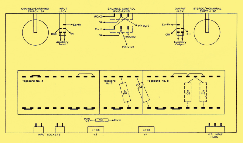
Suggested layout of components - underside view
When the mounting strips and tag-boards have been attached to the rear plate, connections should be made between the valve-holders and the components on the tag-boards. (The valve-holders should be mounted so that the valves will be on the outside of the completed chassis, and screening cans should be fitted.)
The ganged potentiometers RV22-RV122, RV26-RV126 and RV28-RV128 should be mounted on the front panel of the chassis, and the other components which make up the tone-control network should be connected to them. The balance control RV16-RVl16 and the switches SA, SB, SC should also be connected to the front panel, which should then be bolted to the back panel. The remaining components should be connected in position as indicated in the general layout diagrams of tag boards shown above. Details of the selector switch are given below.
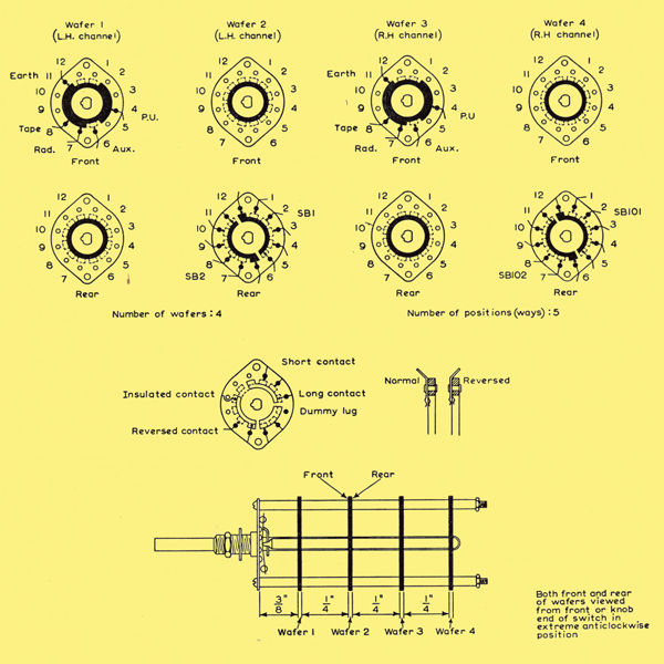
Wafer details of input-selecting switch
Performance
The values for hum and noise in the pre-amplifier which are quoted for each input position have been measured with each channel connected to a 20 W power amplifier. The measurements were made at the output socket of the power amplifier when the input terminals of the pre-amplifier were open-circuited. The frequency-response curves were also obtained with this combination of pre-amplifier and power amplifier.
The sensitivity figures given below provide an output of 250 mV when the full anode load of the second EF86 is used. All measurements were made with the balance control set for balance.
Pick-up Input Positions
Equalisation curves for magnetic and the crystal pick-up positions are drawn below. The difference in sensitivities between the positions for microgroove and 78 rpm records is achieved by the different amounts of feedback provided at positions (d) and (e) of the switch SB1 (SB101).
Magnetic Pick-up Position: input impedance 100 kΩ (approx.).
Sensitivity at 1 kHz: (a) microgroove 5 mV (b) 78 rpm 15mV.
Cross-talk at 1 kHz: (a) microgroove 50 dB below 20 W (b) 78 rpm 60 dB below 20 W
Hum and noise: (a) microgroove 58 dB below 20 W (b) 78 rpm 59dB below 20 W
This arrangement is most suitable for pick-up heads of the variable-reluctance type, but moving-coil types which have higher outputs can be used if a larger value of series resistance R4 is included.
Crystal Pick-up Position: Input Impedance 100 kΩ
Sensitivity at 1 kHz: (a) microgroove 70 mV (b) 78 rpm 210 mV
Cross-talk at 1 kHz: (a) microgroove 48 dB below 20 W (b) 78 rpm 18 59 dB below 20 W
Hum and Noise: (a) microgroove 58 dB below 20 W (b) 78 rpm 59 dB below 20 W
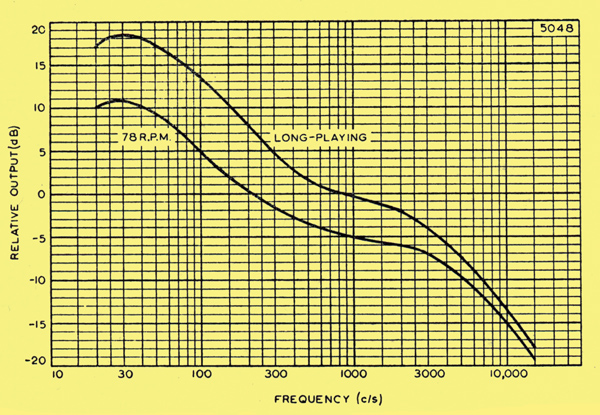
Equalisation characteristic for pick-up input
Low- and medium-output crystal pick-up heads can be used with this position. The input is loaded with the 100 kΩ resistor R6 in order that its characteristic shall approximate to that of a magnetic cartridge, and to allow the same feedback network to be used. This produces the best compromise with most types of pick-up head. However, if the head is not suitable for this form of loading, or if its output is too high, then it can be connected to the auxiliary input socket, the function of which is discussed below.
Tape Playback Position
Input Impedance: 80 kΩ (approx.)
Sensitivity: at 5 kHz 4.0 mV
Cross-talk: at 1 kHz 49 dB below 20 W
Hum and Noise: 54 dB below 20 W
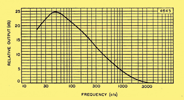
Equalisation characteristic for tape playback input signals
The equalisation characteristic used for this position is shown above. For frequencies above 100 Hz, the curve follows the CCIR characteristic, but below this frequency, slightly less boost is used. The channel is intended for replaying pre-recorded tapes using high-impedance heads, and the characteristic adopted results in good performance with these heads. If a greater sensitivity is required, the value of the resistor R3 can be decreased until the desired sensitivity is obtained.
Radio Input Position
Input Impedance: 1 MΩ
Sensitivity: 330 mV
Cross-talk: at 1 kHz 49 dB below 20 W
Hum and Noise: 58 dB below 20 W
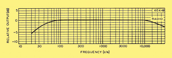
Frequency-response characteristic for radio input signals
The frequency-response characteristic for this position is given above. With the values of impedance and sensitivity quoted above, this channel should meet most requirements. Other values can easily be obtained, however, by altering the feedback resistor R7 and the series resistor R2. If the input impedance of the channel is too high, it can be reduced by connecting a resistor of the appropriate value between the input end of R2 and the chassis.
Auxiliary Input Position
It can be seen from the circuit diagram that the auxiliary position is identical with the radio input channel. The input with the component values shown can therefore be used for high-output crystal pick-ups, for example, or for tape pre-amplifiers. The auxiliary input is taken to a jack socket on the front panel of the equipment. The insertion of the jack disconnects the coaxial input socket on the back of the chassis.
Tone Controls
The treble and bass tone-control characteristics of the pre-amplifier are shown below. These indicate that an adequate measure of control is provided in the unit for most applications.
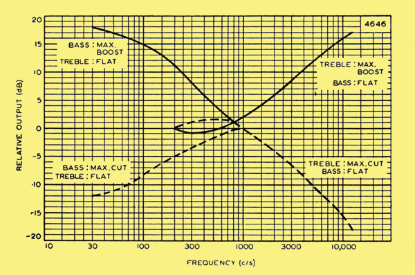
Tone-control characteristics Low-impedance controls have been adopted so that any capacitance resulting from the use of long coaxial leads between the pre-amplifier and main amplifier will have a minimum effect on the output impedance of the pre-amplifier.
Harmonic Distortion
The total harmonic distortion of each channel of the pre-amplifier is less than 0.15% at normal output levels. At outputs of ten times this level, the harmonic distortion is only 0.24 %.
Auxiliary Output Position
An additional output from the second EF86 of each channel is available at this position, enabling a record of programme material to be made with tape equipment. This additional output is taken to a jack socket at the front of the chassis. The voltage at the auxiliary output socket of each channel is about 250 mV and this output is available at a low impedance. Recording equipment plugged into this socket should not have an impedance less than 500 kΩ The tone controls are inoperative when this output is used.
DC Conditions
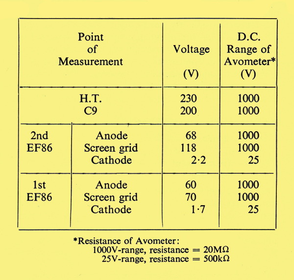
DC conditions in each channel
The DC voltages in each channel should be tested with reference to the above Table. The results shown in this table were obtained using an Avometer No.8 (20,000 Ω/per Volt).
List of Components
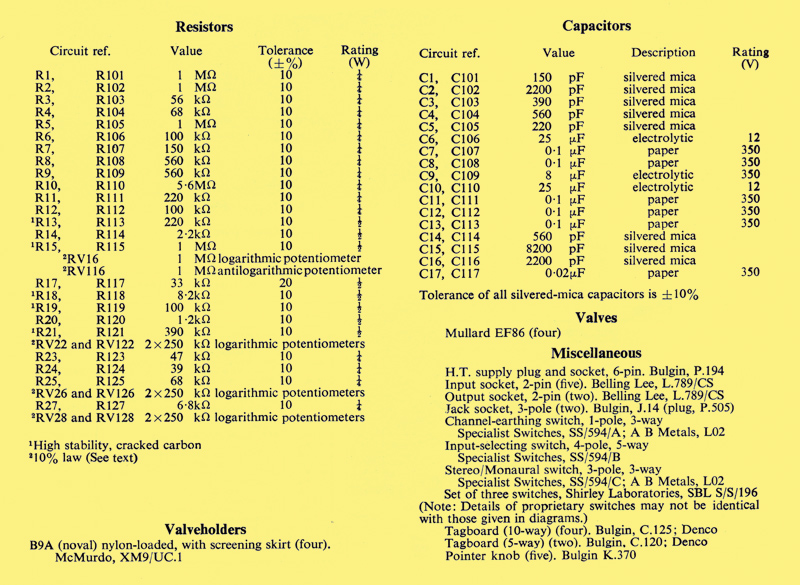
List of components
|