|
The Diode Valve
The diode valve is so called because it has just two electrodes – the cathode and the anode.
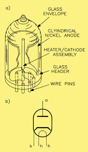
(a) Construction of a modern diode valve (indirectly heated type), (b) circuit symbol for a diode valve.
These correspond to the two electrodes of the original diode valve mentioned above, the cathode being the electrode that is heated and emits electrons, and the anode being the electrode that collects the electrons (notice also that these terms have passed forward into semiconductor phraseology - cathode, anode, emitter, collector!).
Since electrons are negative charged particles, they will only be attracted to the anode if this is given a positive potential with respect to the cathode. This explains why the valve only conducts in one direction, from cathode to anode, and not vice versa. It also explains the choice of the word 'valve' to describe the device, since a valve is, by definition, a one-way device. The Americans, however, never cottoned on to this terminology and always refer to them as 'vacuum tubes'.
The magnitude of the current flowing in a diode depends upon the number of electrons emitted and the magnitude of the voltage applied to the anode (known as the anode voltage Va). The amount of electron emission depends upon the temperature of the cathode, which is fixed by the voltage supply to the heater, this being a constant value. The only true variable is, therefore, the anode voltage. The action of the latter in controlling the anode current can be explained as follows.
As we now know from the foregoing, the cathode is normally surrounded by a cloud of electrons known as the space charge. With zero anode voltage there is no current flow, and there is a state of equilibrium between the electrons being emitted and those falling back onto the cathode's surface, The application of a small positive voltage to the anode causes some of the space charge electrons to be attracted to the anode, resulting in a small anode current flow. The gaps created by these electrons leaving the space charge are filled by further emission from the cathode. Electrons arriving at the anode flow to the positive supply terminal, while at the same time an equal number of electrons leave the negative supply terminal for the cathode. This gives rise to a continuous current flow around the circuit, which may be detected by an ammeter placed in, say, the anode lead. The picture below shows an illustration of this.
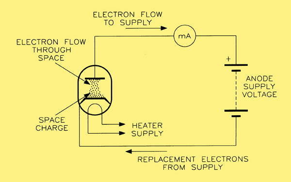
The flow of current in a diode valve.
Diode Static Characteristics
We now start getting into the ways in which specifications for thermionic devices are presented. For the diode, these illustrate clearly the dependence of anode current upon anode voltage.
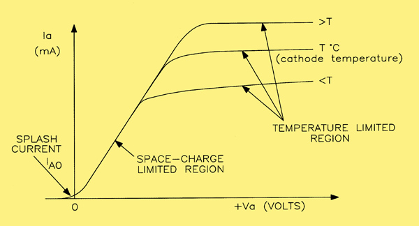
The static characteristic of a diode valve.
Above three curves have been drawn for different values of cathode temperature, although in practice, as explained earlier, the cathode is held at a constant temperature.
It is interesting to note that:
- The current is not exactly zero when the anode voltage is zero, but has a value (Iao) of a few micro-amperes. This is known as the 'splash current' and is the result of a few high energy electrons that manage to cross the inter-electrode gap even without an attracting potential.
- In the space-charge limited region, the characteristic is nearly linear (actually following the 'three-halves' power law: Ia is proportional to Va-3/2).
- In the temperature limited region there is little change in la even though there are large changes in Va. This is because the anode is collecting electrons at the same rate as they are being emitted by the cathode.
- No significant current flows when the anode is negative with respect to the cathode.
The Anode Slope Resistance ra
It is worth introducing this parameter at this time since it is one that we shall make use of later in discussing the performance of more complex valves. It is defined as shown below,
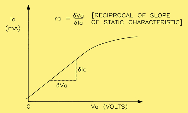
Defining anode slope resistance for a diode valve.
and is the value of resistance obtained by dividing a small change in anode voltage by the corresponding change in anode current. It is therefore the reciprocal of the slope of the static characteristic, and varies with the operating point, although fairly constant over much of the space charge limited region. This is a real value of resistance, since it represents the opposition of the valve to alternating quantities.
Series Circuit Operation
It is usual to operate a diode valve, which is clearly a non-linear device, in series with a resistive load, the latter being a linear device. It is possible to predict how the voltages and current in the circuit will vary by using a graphical construction.
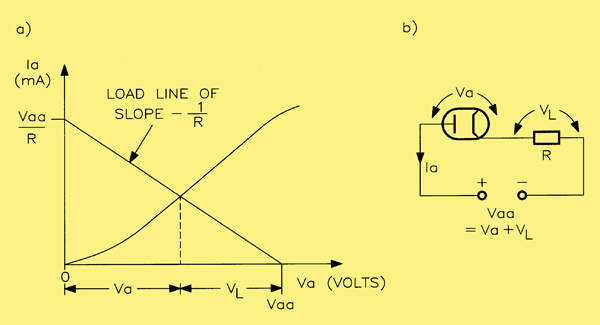
(a) The load line for a diode valve. (b) the diode in series with a linear resistive load.
The second image shows the diode in series with its load and defines the voltages and currents in question. A 'load line' of slope -l/R is drawn between the two points: Ia = Vaa/R Va = 0 and Ia = 0, Va = Vaa. As in solid state practice, the end points of a load line define zero conduction and maximum conduction, the latter being dependent upon the values of supply voltage and load resistance. Any other points on the load line imply intermediate levels of conduction. By dropping a construction line from the intersection of the load line and the static characteristic, we can see how the total supply voltage Vaa is divided into the two separate voltages Va (the voltage across the diode) and Vl (the voltage across the load).
The Dynamic Characteristic
By taking a number of different values of supply voltage Vaa (as would happen if the supply was alternating, for example) and assuming a constant value for the load Rl then, by drawing a separate load line for each value of supply voltage, the dynamic characteristic can be obtained, as shown below.
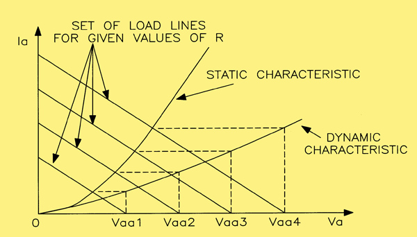
Obtaining the dynamic characteristic for a diode valve and its load.
The points on the dynamic characteristic are obtained by projecting, horizontally, the intersection of a load line and the static characteristic until it in turn intersects a vertical line drawn from a supply voltage value. Since the dynamic characteristic is drawn for a range of values of the supply voltage, this implies that the latter is varying, in other words it is an alternating supply rather than DC, as is the case in rectification.
|