|
In the final part of this series, we conclude last month's discussions on practical audio amplifier systems with the final link in the chain between pick-up and loudspeaker - the power output stage.
The previous amplifier stages have been concerned with producing a faithful replica of the input signal, but at a larger voltage amplitude. The function of the output stage is rather different and certainly more demanding. Because it requires work to drive the speech coil of a loudspeaker, and because work equates to power when we introduce the time element, the output stage must produce large excursions of current as well as voltage - and it must do so with the minimum amount of distortion being introduced. This means that the output valves must be capable of passing large current flows, which implies a heavy emission of electrons from the cathode surface in the first place. There are two factors that limit the amount of current that a valve can carry They are:
- the surface area of the cathode capable of emitting electrons, coupled with the power input to the heater
- the amount of heat that can be dissipated at the anode without causing degradation of the valve's performance, eg, the emission of gases from the surface, which would seriously impair the operation of the valve by causing collisions between the gas molecules and the electrons in transit; excessive heat could also cause failure of the anode structure.
It is obvious from the above points that valves intended for high power applications (using the word 'high' in a relative sense, since one man's watt is another's kilowatt!) must have larger electrodes than those intended just for voltage amplification.
Triodes versus Pentodes
These two types are obvious contenders for the role of output valve; for the moment we will lump beam tetrodes in with pentodes. What we need to consider is how well each type of valve will be able to handle the task, given the rather stringent requirements that apply Let us consider triodes first.
lf the characteristics were absolutely linear and parallel, no amplitude distortion at all would result. Both half-cycles of the signal input would produce equal swings at the output, each being a faithful copy of the input.
The mutual (grid) characteristics for triodes tend to be both linear and parallel, which means that swings of the signal voltage along these characteristics should not cause too much distortion in the output (we won't, at the moment, quantify how much distortion is tolerable), so this is a plus point for the triode. On the other side of the coin, however is the low gain of the triode. This means that, for a given output signal amplitude, the input signal has to be fairly large if the stage is to be driven fully At the same time the triode also takes a great deal of current from the HT supply, so is not very economical in terms of power consumption (when compared with its amplifying capability).
The type of amplitude distortion that the triode does produce is largely second harmonic. Thus, an input signal at, say 400Hz would have, after amplification, a significant amount of an 800Hz component also. This fact is, as we shall see later not as serious as it might at first appear, since it is relatively easy to reduce this type of distortion to acceptable proportions.
Looking at the pentode now, and bearing in mind some of the deficits listed above for the triode, one advantage that we can call to mind immediately is going to be its higher voltage gain, allowing the use of a smaller input signal in order to obtain a given output. Also, it takes less HT current, and so is more economical with supply power than the triode. However; its mutual characteristics are not as linear or as parallel as those of the triode, though it is possible to compensate for this deficiency.
As far as harmonic distortion is concerned, the dominant harmonic produced here is the third harmonic. Eliminating this is not as easy as getting rid of even order harmonics: 2nd, 4th, etc. One point of comparison that can be made with triodes, that we shall see is significant, is the value of the anode slope resistance, ra. In triodes this is quite low, whereas in pentodes it is by comparison generally extremely high.
The Triode Output Stage
Any valve amplifier, being an active device that is delivering a signal to a load, can be considered in a general case to be a generator. Any generator cannot avoid having an internal resistance, and the value of this internal resistance will determine the optimum value of load impedance into which the generator can deliver its maximum power. For valves, the internal resistance is the parameter ra, this being the reciprocal of the slope of the output characteristics, as we have seen in Part One and Part Two, and so is quite clearly the output resistance of the valve when feeding a load.
The maximum power transfer theorem states that ''a generator delivers maximum power to a load when the source resistance of the generator equals the load resistance''. Before anyone reaches for pen and paper to tell me that I am wrong, let me just add that this theorem as stated applies when the load is resistive. If the load is reactive then maximum power is transferred to the load when the load impedance has a value that is equal to the conjugate of the generator impedance. If the word conjugate isn't understood, don't worry about it; it comes from complex algebra, which I have no intention of going into here!
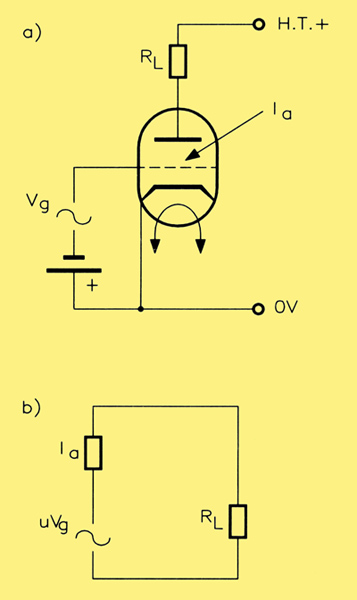
The valve as a generator; (a) actual triode circuit (without bias components) and (b) the AC equivalent circuit.
The figure above shows the valve represented as a generator Figure (a) shows the triode (it could equally well be a pentode) with an input signal Vg, a load RL in the anode circuit and the internal resistance ra. The grid bias voltage is represented by a battery and since this voltage is DC Figure (b) shows the equivalent circuit which can be used to analyse the performance of the amplifier This comprises three components: a voltage generator μVg, which represents the valve action and two resistances: ra, the generator internal resistance; and RL, the load resistance. In the specific case of the valve, whether triode or pentode (in theory at least), the maximum power will be transferred to the load when the latter is equal to the ra of the valve. This raises a problem immediately.
The load on an audio output stage is the speech coil of the loudspeaker it is totally impracticable to wind such a speech coil so that it has an impedance anything like that of the ra of even a triode valve, which will be of the order of thousands of ohms! A practical value for the speech coil impedance is unlikely to be more than a few tens of ohms (eight ohms (8Ω) is a common nominal value). From this it is quite obvious that it is impracticable, in the case of valves, to connect the speech coil directly into the anode circuit of the output stage as the load. There are other considerations that make this undesirable anyway, but the above argument, on the grounds of load and source impedances, should make it clear why this course of action cannot be undertaken.
The Output Transformer
The answer is to use an output transformer with a step-down turns ratio. The required ratio 'n' can be calculated from a simple formula, which is as follows:
n = √(load required by valve) / (resistance of speech coil)
Notice that the above formula says load required by valve and not actually the valve's ra. This is because the load presented to the valve by the loudspeaker through the transformer is not resistive and it has been found in practice that the load that the valve needs to see is approximately equal to twice the ra of the valve.
As an example, if the triode in question had an ra of 8,000Ω and the speech coil resistance was 16Ω (using convenient figures for ease), then twice ra is 16,000Ω and the turns ratio needed is equal to √1,000, which is approximately 33:1.
The penalty that one has to pay by making the effective triode load equal to twice the valve's ra is an increase in the drive voltage required for full output.
Design of output transformers for quality audio reproduction requires great care. In particular the primary inductance must be as high as possible (necessitating a bulky transformer) if it is to offer a constant impedance to the valve at all frequencies of interest.
Modern cores are not made of 'ordinary' electrical steel as may be found in a mains transformer but of a higher quality purer stuff with superior magnetic performance; this also makes it possible to keep the bulk down to reasonable proportions, certainly modern examples are a good deal smaller than their early equivalents.
Other factors such as self-capacitance and leakage inductance must also be optimised if reproduction at the high frequency end of the spectrum is not to suffer. This is usually achieved by not winding the former in the 'normal' way like you would with a mains transformer Instead, both primary and secondary windings are split up into sections and interleaved with each other: some of these arrangements can be quite complex and, to go really 'over the top', one layout incorporates a split bobbin, where the order of the layers on one half are reversed on the other half. Add to this a choice of secondary taps for different speaker impedances, and it can be appreciated that manufacture can be extremely labour intensive, and, hence, valve output transformers can cost a small fortune if you want genuine Hi-Fi quality. For more information on the subject, see the small book Coil Design and Construction Manual by B B Babani (available from Maplin, Code RH53H, Price £2.50) which came out as a first edition in 1960, and gives detailed guidelines on how to make your own. We wouldn't recommend designing and making your own output transformer however: there are, fortunately, still a few competent manufacturers around.
Tetrodes and Pentodes
In contrast to the triode, both of these types of valve have extremely high values of ra that require careful matching to the loudspeaker impedance. The rule regarding triodes does not work in these cases, and it has been found that these valves work best when they see an effective anode load that is between one-third and one-sixth of their ra value. Care is required in the design of output stages using such valves since, otherwise, they can generate an excessive amount of distortion. In general, the safest technique is to choose the load value which is recommended by the maker of the valve.
Although the beam tetrode may often be considered as the equivalent to a pentode (especially since they are alter- native answers to the same problem of the inter-electrode capacitance Cag), there are significant differences due to their different modes of operation. One of these differences is the type of amplitude distortion that each introduces into the amplified signal.
In the case of pentodes, the distortion is principally third harmonic with only a little second harmonic; this is the opposite to the beam tetrode, where mostly second harmonic distortion is produced. Thus, in terms of harmonic distortion, beam tetrodes behave more like triodes.
Push-Pull Amplification
There are several ways of approaching the design of valve power output stages:
- Single-ended, where the output transformer is in the anode circuit.
- Parallel operation, where two or more valves are connected in parallel in order to boost the power output, the output transformer being again in the common anode circuit.
- Push-pull operation where two valves (or sets of paralleled valves) are driven alternately by the input signal, each valve having half of the primary winding of the output transformer in series with its anode, the centre tap of this transformer being connected to the HT supply positive line.
We can dismiss both (a) and (b) immediately on the grounds that, since the primary winding carries the full anode current in one direction only its core would have to be excessively large or specially constructed in order to avoid saturation arising from the quiescent DC. Again the Coil Design and Construction Manual shows how this is done; the common arrangement is where the magnetic circuit is effectively broken by introducing a thin layer of waxed paper or similar to separate the core into independent stacks of 'E' and 'I' sections. The gap reduces the core's sensitivity to DC, yet allows alternating magnetic lines of force to pass through. LF response is critically linked to the choice of gap spacing, so tolerance must be tight. Many consumer quality radio-grams and record players et al used this type of output stage, but it is not worthy of serious consideration, especially as the type of harmonic distortion introduced by the output valve(s) cannot be reduced by this type of connection.
However in the case of (c), push-pull operation, the DC anode currents flow in equal and opposite directions in the half-primary windings, and so their fluxes cancel out. Saturation is thus avoided, even with relatively small cores, the core size now being dictated by the consideration given above, of providing a constant load at all frequencies. The second advantage that arises from the push-pull connection is the cancellation of all even order harmonics. The image below shows the arrangement of one possible type of push-pull output stage.
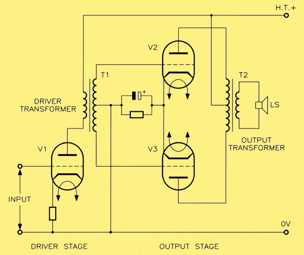
A Push-Pull output stage using triodes.
Valve V1 is the driver stage and valves V2 and V3 form the push-pull output stage. The phase-splitting action is performed here by the use of a driver transformer T1, in which the secondary winding is centre-tapped to 0V and so provides a pair of equal, anti-phase voltages to the grids of the output valves as well as DC bias. With no signal input to the driver stage, both output valves draw only their quiescent current, and this flows in opposite directions in the half-primaries of the output transformer T2.
When a signal is being amplified by V1, both ends of the driver transformer T1 are at opposite potentials with respect to the centre-tap, the latter being connected to the cathodes of both output valves via the cathode bias components R1 and C1. Thus, as the grid of one output valve is being driven in one direction, say positively, the grid of the other output valve will be driven in the opposite direction, in this case negatively. The terms positively and negatively are here used in a relative sense, since whether the signal voltages are actually positive or negative with respect to 0V will depend upon the way in which the output valves are biased. The classes of bias possible with output valves are illustrated by the mutual characteristic shown below.
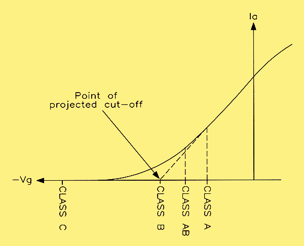
Classes of bias.
Classes of Bias
These are more commonly used to describe 'classes of amplifiers'. Taking Class A first of all, this is the bias method commonly employed with most single-ended amplifiers, i.e. not wired in push-pull. The valve is biased to the mid-point of the characteristic such that the quiescent anode current is large, and the signal swings cause equal changes in this current for both half-cycles. Distortion is minimised, but efficiency is low because of the high DC power input required to obtain a given AC power output. The available AC power output is also reduced, because the valve is contributing to both positive and negative half-cycles of the output signal, and having to do it within its available total signal excursions.
If, instead, the valve is biased to the point of projected cut-off, the valve is then operating in Class B. The quiescent anode current is extremely low giving very high efficiency but the amount of distortion introduced is high, making this mode unsuitable for quality reproduction. Its main application is in public address systems where quality is less important than cost.
A compromise class of bias then is Class AB, where the bias point lies between those for A and B. This gives an improvement in efficiency and possible power output over Class A, with better quality than can be obtained with Class B. Class AB actually divides into two sub-classes, depending upon how hard the grids are driven. In Class AB1, drive is restrained so as not to cause grid current to flow; in Class AB2, grid drive is increased and grid current flows at the peaks of the positive half-cycles.
Finally, in Class C operation, the grids are biased well beyond cut-off and are driven very hard in order to make anode current flow in short pulses, just at the peaks of the positive signal half-cycles. This type of bias is restricted to radio-frequency operation, where the pulses of current merely excite a resonant circuit in order to produce a full sinusoidal output. So now you know!
Harmonic Cancellation
Because of the fundamental way in which push-pull output stages work, the signal currents in the output valves flow in opposite directions in the output transformer's secondary winding. The magnetic flux that links with the secondary winding of this transformer induces voltages that are additive in this secondary Thus, a positive half-cycle developed in valve V2 at one instant causes a corresponding voltage to be developed in the secondary winding; this is followed by a negative half-cycle produced by valve V3, which also induces a similar voltage in the secondary winding. As a result, the secondary voltage appears as a continuous voltage, compounded from the successive efforts of the two push-pull output valves working separately but in co-operation.
However any even order harmonics, 2nd, 4th, 6th, etc., generated by the output valves cause opposing magnetic fluxes in the primary winding which, consequently cancel out. No even order harmonics appear in the secondary winding. This is a major advantage of push-pull operation. It is obvious that this is of more significance when triodes or beam tetrodes are used, since this is the type of harmonic distortion that these valves generate. This somewhat dampens the popular idea that the main characteristic of such amplifiers is that they generate lots of 2nd order harmonic distortion!
Value of Anode Load for the Output Stage
The actual value of the anode load in push-pull operation is not the same as that calculated for single-ended operation. Again, the best bet will be the figure provided by the valve makers since this will have been computed to give the minimum amount of odd order harmonic distortion. In pentodes, it is third harmonic distortion that is the major type, and it is possible to minimise this by a suitable choice of load. In fact, it is essential to do this, since push-pull operation does not result in any reduction in the odd order harmonic content. It has been found that reducing the value of anode load substantially below the nominal value reduces third harmonic distortion and increases second harmonic distortion, the latter then of course being cancelled by the push-pull connection.
Negative Feedback
It is possible to write a book on this subject; many have already done so and I have no intention of adding to the published material. Suffice it to say that it is a matter of great importance in the design of audio amplifiers, of any type. Thus, the theory is not specific to valve amplifiers. Its benefits are well-known in reducing distortion of all types, in giving gain stability and in coping with the resonance problems of loudspeakers. That is all that need be said about it here.
Examples of Hi-Fi Audio Amplifiers
We shall now have a look at a few audio amplifier circuits which will illustrate the various approaches that designers have adopted in the past.
The Garner 10W Main Amplifier
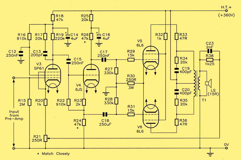
The Garner 10W Main Amplifier
The first of these is shown above and was designed by Major H H Garner in the early 1950s. It doesn't have any pretensions to exceptional performance but is, nonetheless, a creditable performer according to G A Briggs, who tested it exhaustively at the time. It was paired with a preamplifier; which had the obligatory bass and treble controls as well as input switching for pick-up and radio, and compensation for LP and 78rpm records.
The circuit is fairly simple and the line-up is quite conventional for those days. (The 'line-up' was the collective expression used for all the valves.) No miniature valves were used; these were still a little way off in time for general use. The output valves were the popular 6L6s and these were somewhat under-run. The distortion figures may not seem exciting but were seen as being adequate for the purpose. At an output power of 5W the THD was 0.8%, which rose to 1.5% at 10W output.
The pentode first stage, V3, included overall negative feedback from the output transformer secondary winding. This could be varied between zero and 22dB of NFB (Negative FeedBack). Apart from the fact that this varies the sensitivity of the amplifier no justification was offered for this arrangement. The points that were made were as follows.
- Since the 6L6 output valves made no great demands upon their input drive, a concertina phase-splitter was considered adequate, with balancing of the bi-phase outputs being achieved simply by matching the values of load resistors R24 and R26.
- Because of the high input impedance of the phase-splitter; it was possible to use a pentode first stage to give both high gain and good top response.
A 10W Amplilier for Mobile Public Address
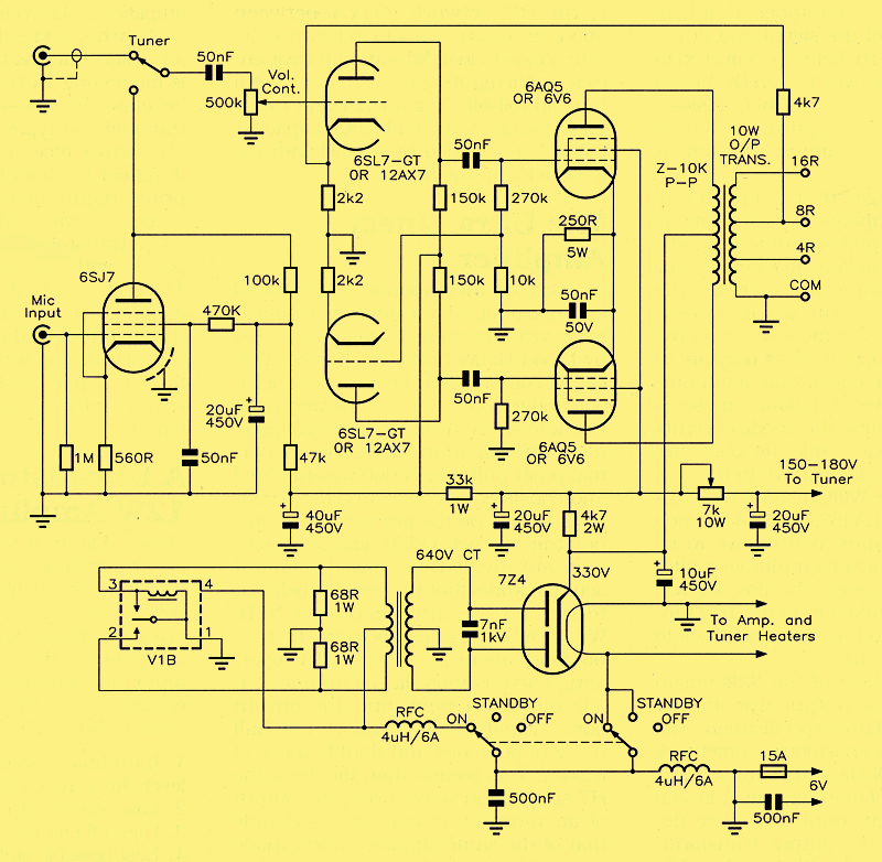
A 10W Mobile Public Address Amplifier
The circuit above shows an amplifier that appeared in the American magazine Radio-Electronics in March 1957. This was published in response to a letter from a reader who wanted a power amplifier both for his FM tuner and for mobile PA requirements. Since it had to be mobile, it couldn't use a mains supply, so a feature of the design was a vibrator pack, to convert the low level vehicle DC (6V no less) into the higher level HT required by the amplifier.
The first stage, V1, was a 6SJ7 pentode, used purely as a microphone preamplifier and giving enough gain to allow any high output, high impedance crystal or dynamic microphone to be used.
A separate tuner input was provided that tapped directly into the grid of one half of the double triode V2a. Here we see a choice offered between the older and larger 6SL7GT valve and one of the newer all-glass the 12AX7 (ECC83). The output valve is another popular choice of the day the 6V6; or a 6AQ5 could be used instead. The phase splitter is of the paraphase type with V2a as the first stage and V2b as the second stage. Anode loads are 150k and these feed the purely conventional output stage comprising pentodes V3 and V4. Overall NFB was taken from the 8Ω tapping on the output transformer secondary winding to the cathode of V2a. A grid signal for V2b is contrived by tapping the grid leak resistor chain for V3.
The Craftsman C-500
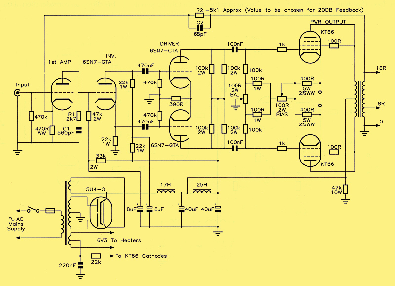
The Craftsman C-500 Williamson Amplifier
In the May 1956 issue of Radio-Electronics there appeared a circuit for a typical 'Williamson' amplifier, the 'Craftsman C-500', shown above. For those not in the know, Williamson was a famous name at the time in the field of Hi-Fi amplifiers and belonged to D T N Williamson who was employed as an engineer with the British firm of Ferranti. His Craftsman C-500 amplifier uses a pair of KT66s, which were very popular high power valves in those days. Although they are actually beam pentodes, they were connected as triodes by wiring the screen grid to the anode via a 100 Ω resistor (The use of the KT66 in triode mode is validated by applications data; not all pentodes and tetrodes may automatically be connected up this way).
Note also the circuit symbols used for them. Do you remember in Part Four mentioned that often beam tetrodes are given pentode symbols in circuits, whereas the beam tetrode version should really be used for clarity? Although the KT66 is classified as a pentode, it has beam forming plates in place of a suppressor grid, and is practically indistinguishable from a beam tetrode in construction. Some would say the KT66 is a classic beam tetrode - ed.
In this circuit the first stage, V1a, is a pre-amplifier whose output drives a concertina phase splitter V1b, thus neatly putting both stages into one double triode. Note also that, as was mentioned in Part Six on the subject of phase splitter configurations, that here is an example of the signal grid of the splitter stage, V1b, being DC coupled to the anode of V1a, which then DC biases V1b. This makes a local bias resistor network and a coupling capacitor unnecessary, a saving in component count.
The third stage driver is a push-pull type whose anti-phase outputs directly drive the push-pull output stage grids, and is included to develop a healthy driving voltage swing and increase the open loop gain of the whole system, bearing in mind the modest gain of the output valves, operating as they are in triode mode (see discussion about output triodes above). A 'balance' preset is provided to equalise the anode currents of the output pain while the 'bias' pre-set sets the net bias current in the output stage. In the Williamson design this is typically 125mA (62 to 63mA for each valve). These adjustments have to be made with the aid of a multimeter after temporarily removing the link shown. Overall NFB is taken from the 16Ω tapping on the output transformer back to the cathode of V1a.
It was a feature of the Williamson designs that the output transformer was of a superlative specification. The bandwidth was enormous, sometimes in excess of 100kHz, with extremely low distortion and of massive size. It is said that Williamson amplifiers were designed around the output transformers. The wide bandwidth introduced in stability problems, however in the presence of NFB. It was possible to alleviate this by including a bypass network within the loop that was only effective at frequencies at or above 100kHz. This is the RC network R1 / C1 between anode and ground of V1a. Its function is to load V1a at high frequencies, reducing its gain and ensuring a top end roll-off. As a further anti-instability measure, a small value capacitor C2 was also added in parallel with the feedback resistor R2.
The Ultra Linear Amplifier
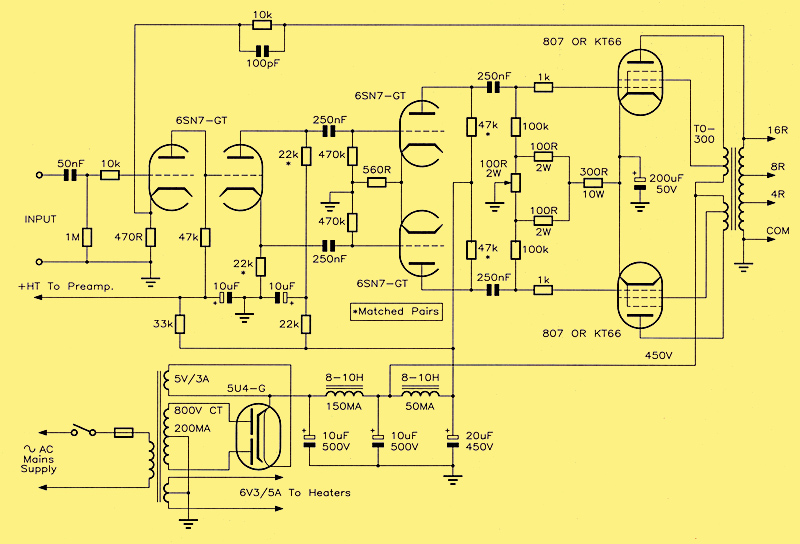
The Williamson Ultra-Linear Amplifier
In 1952 or thereabouts, an unusual output circuit, which had been patented some years previously was resurrected by David Hafler and Herb Keroes. This circuit combined the best features of triode and tetrode/pentode operation and was known as the Ultra-Linear configuration. The important change to the normal push-pull connection was minimal and consisted of connecting the screen grids to taps on the primary of the output transformer Oddly enough, opinions are divided on how the circuit actually works, but the secret is believed to rest on the introduction of NFB. Whatever the modus operandi, there is no doubt about the benefits. The operating curve is more linear than for triode operation even, and the output power capabilities are about one-half those of pentodes and double those of triodes. 'l"his means that, for the same HT supply and signal drive, the output of an ultra-linear amplifier is double that of the same amplifier when triode connected. In fact, distortion at low levels is reduced as is the phase-shift at high frequencies. This makes it possible to increase the degree of NFB without incurring any further instability penalties. The Ultra-Linear Williamson amplifier is shown above.
Another aspect of the design of amplifiers such as the Williamson types is interesting. At the time, valves might be classified loosely as being either transmitting types or receiving types. The former type of valve was obviously designed for handling high powers, a prime requirement for audio output stages. It was natural, therefore, to adopt transmitting valves for Hi-Fi purposes, with consequent advantages. They didn't make too stringent a demand upon the driver stages as far as the amplitude of the driving voltage was concerned, and they were operating on the linear parts of their characteristics when delivering the high powers required.
A Low-distortion 12W Amplifier
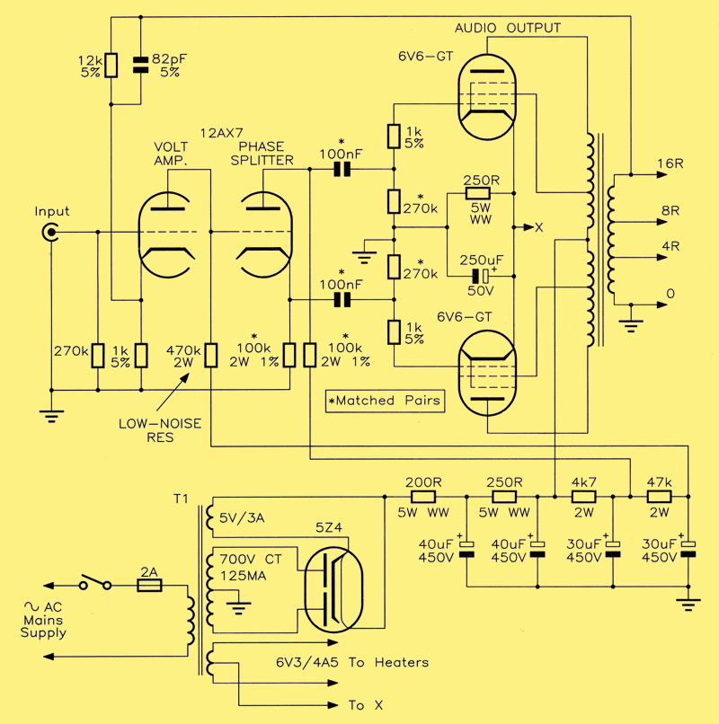
Design for an Ultra-Linear 12W Amplifier
Finally another ultra-linear amplifier circuit, but rather simpler than the Williamson version. The power output from this is a modest 12W but even this is often considered to be adequate for the average living room. I reproduce here the designer's original criteria, taken from the August, 1958 issue of Radio-Electronics.
- lnaudible distortion at all feasible levels (in a 10 x 15ft. room).
- Low source impedance.
- High efficiency.
- Best possible stability characteristics.
- Hum and noise below audibility (under specified conditions).
The designer concentrated most of his efforts on consideration of the degree of NFB needed to meet his criteria 1 to 4 above, and opted for the ultra-linear mode of operation, using a pair of 6V6s. To obtain this type of operation with these valves requires the output transformer primary winding to be tapped at 25% on each side of the centre-tap. The choice of output transformer from what was on the market at the time, fell on the Acrosound TO-310, which had a rating of 10W over the bandwidth 20Hz to 30kHz, and 20W over the reduced bandwidth of 30Hz to 20kHz, the latter being adequate for good reproduction.
The circuit itself uses a 12AX7 (ECC83) double triode, with one section, V1a, being a voltage amplifier directly coupled to a concertina phase-splitter This gave a number of advantages.
The DC coupling eliminates one stage of capacitive coupling which gives greater frequency stability Placing the phase splitter directly before the output stage (which is possible due to the low drive requirements of 6V6s) eliminated the hum frequently resulting from the large potential difference between the heater and the un-bypassed cathode of V1b, being amplified by a further push-pull driver stage. The anode load of the voltage amplifier acts as the grid leak of the phase splitter thus allowing the voltage amplifier to work into a very high impedance, so that high gain with low distortion are obtained from the first stage of amplification.
Efforts were made to improve the performance by matching pairs of resistors and some capacitors (if possible) to within 1% of each other These are indicated on the circuit diagram. It seems, from the comments made upon completion and testing, that the amplifiers performance lived up to expectations.
That just about concludes this series on Valve Technology, which has been restricted to audio applications only, and this is now one of the few fields left where valves still survive - we haven't even mentioned radio, TV, Instrumentation and industrial applications, which of course at one time valves had to cater for also! The only other area where valves are still in common use is for radio transmitters (a very large, high voltage, high power triode operating in class C).
We hope you have found the series both interesting and informative, and that it has answered a lot of questions you may have had about these devices. You may now be sufficiently better informed to try some experiments of your own. Elsewhere in this issue you will find details for Maplin's own valve power amplifier project, which closely resembles Mullard's '520' ultra-linear design of the late 1950s and early 60s. Happy metal-bashing!
|