|
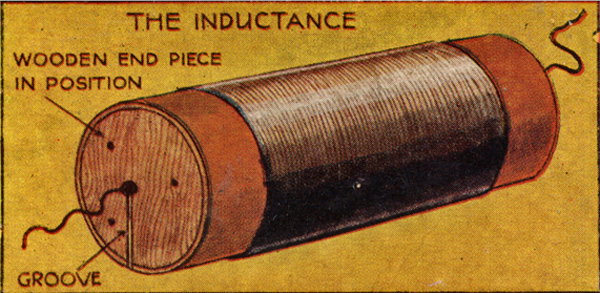
(1) The Inductance.
Procure a cardboard cylinder 6 inches long and 4 inches in diameter, also 0.5lb. of 25 SWG copper wire either enamelled or single-silk covered. The cylinder is dipped in molten paraffin wax and allowed to dry hard. About 0.75 inches from one end bore two small holes 0.5 inches apart, thread wire through one hole and up through the other hole, leaving 4 or 5 inches free. Wind on the wire in close turns, keeping the wire in fair tension until within 0.75 inches of the other end of the cylinder. The last turn should be anchored as at the start. The inductance will then look as illustrated.
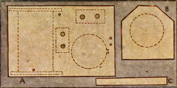
(2) The Baseboard & Side Supports.
From 0.5 inch hard wood cut out Baseboard A 12 x 8 inches on which all the apparatus will be mounted. Also cut two circular pieces so that they fit snugly in the ends of the inductance former, then secure therein with glue or brass boot brads. Prepare two pieces of wood B 6 x 6 inches, and make two cross cuts on each at an angle of 45° from points 2 inches down from upper corners (see diagram). Supports C for baseboard should be 12 x 1 x 0.5 inches. These are screwed to underneath side of baseboard at each end so that base is raised to allow wiring-up (see card 15).
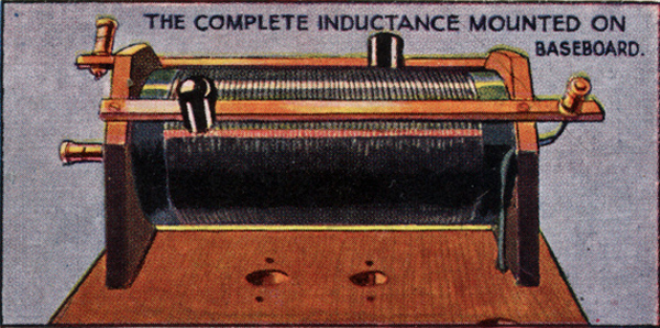
(3) How to Mount the Inductance.
See Card 2 for position of inductance and side supports when mounted on base. Fix side supports to baseboard with brass screws so that inductance will fit tightly in between. A hole should be bored in left hand support to allow fixing of terminal. Centre coil on each support, keep parallel to base, and secure supports on baseboard. The groove (see Card 1) allows wire to connect to variable capacitor. Also, before inductance is permanently fixed the wire is connected to a terminal mounted in left hand support (See T).
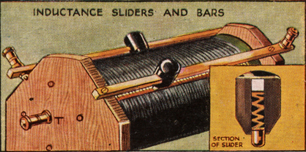
(4) The Inductance Slider and Bars.
Procure 14 inches of 0.25 inch square brass rod and cut in half. Attach to inductance side supports as indicated. On the protruding end of each bar attach a terminal.
The slider is made of a cylindrical moulding of insulating material such as ebonite, through the side of which a square hole is made to take the bar. A brass plunger with strong helical spring is fitted so that effective connection is made between inductance and the bar. The inductance wire is bared in the track of the plunger by rubbing lightly with emery paper.
(5) The Crystal Detector.
The following crystals are most commonly used in the receiver we are describing.
Hertzite - A manufactured crystal used with a fine copper wire helix.
Galena - Used with a copper, brass or graphite point such as a piece of B or BB lead ending in a blunt point.
Zincite with copper pyrites or bornite - this will be found to be a sensitive and constant combination.
In all crystal detectors good specimens are essential and great care in adjustment, both as regards pressure and actual point of contact, is necessary.
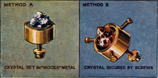
(6) Mounting Crystals.
Place in the brass cup a few chips of Wood's Metal, heat cup gently over clear flame; when metal is in a molten state, set crystal in same with a pair of tweezers. The alloy quickly cools, and crystal is ready (Method A).
Method B for Larger Specimens. Bore and tap three holes in the side of the brass cup and insert crystal. Screw up the three screws previously placed in the tapped holes until crystal is held securely. All crystal cups must have a screw at bottom for fixing to panel & making connections.
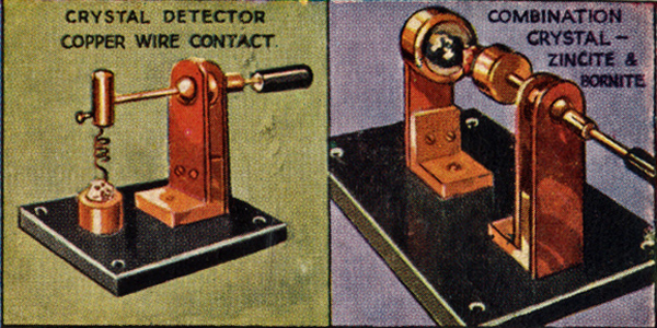
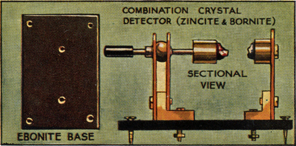
(7) Assembling Crystal Detector.
Parts required:- Strip of ebonite 3 x 2 inches. Two brass angle pieces 0.75 inches wide, each side of the angle being 0.5 inches in length. 3 copper strips 1.375 inches high as illustrated. A ball and socket is required in which slides a brass rod having at one end a crystal cop to take the Zincite if a Perikon Detector is used, or a screw attachment for the metal helix if Hertzite or like crystal is employed. At other end an ebonite knob is fixed for handling purposes. Cards 5 and 7 show clearly how the Detectors are constructed.
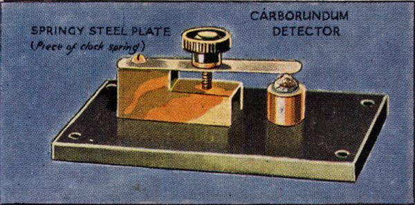
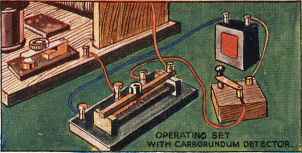
(8) Carborundum Detector.
On an ebonite base 2 x 3 inches is mounted a crystal cup in which the Carborundum is set. Also a brass block to the end of which a steel blade is screwed down securely, the other end of the blade being over the crystal. An ebonite knob fixed to a small length of brass screwed rod is passed through the blade into the brass block, which has been previously bored and tapped, so that the pressure of the blade on the crystal may be adjusted. Connections are made to nuts securing brass block and crystal cup underneath.
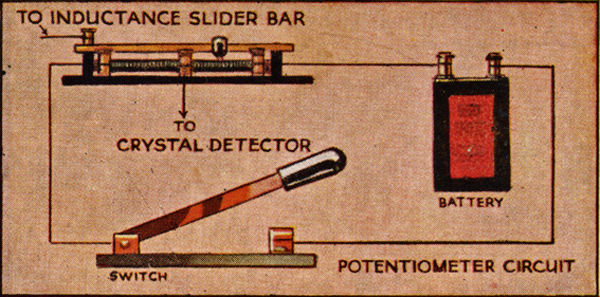
(9) Potentiometer.
When using the Carborundum Detector it is always necessary to connect-up with a Battery and potentiometer. The battery should give 4 volts, and the usual pocket-lamp battery will be found quite useful although a longer life is obtained with larger cells. The potentiometer adjusts the amount of current applied to the crystal, and is constructed so that either a negative or positive potential is used at will. Perhaps a more simple name for the potentiometer is Variable Resistance. Illustration shows wiring diagram to battery.
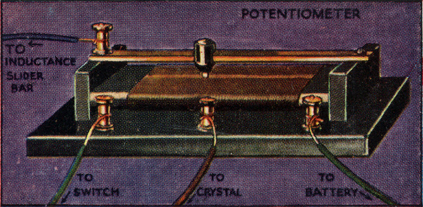
(10) Assembling The Potentiometer.
Wind 20 yards of No. 40 gauge of Eureka Wire (single silk covered) on an ebonite former 4 inches long and 0.25 inches thick, and 0.5 inches wide. Secure ends of wire to two terminals, at either end. Fix former to side supports and mount on a small baseboard. Attach a brass bar and slider, as indicated, carefully clean the insulation off the wire in the track of the slider, and fix a terminal to end of brass bar. Ascertain EXACT centre of coil, carefully attach a length of wire at this point and join to centre terminal on baseboard.
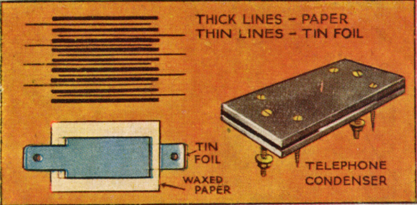
(11) The Telephone Capacitor.
Cut out 11 pieces of paraffin waxed paper 2.5 inches square, also 10 pieees of tinfoil 3 x 1.5 inches. Procure 2 pieces of Ebonite 4.5 x 2 inches and bore four courner holes in each for screwing down to baseboard of set, also 2 small holes for anchoring tinfoil plates by means of nut and bolt through both holes. In wiring up, connections to the bolts will be made underneath through two 0.75 inch holes driiled in baseboard. Pack tinfoil and paper as diagram. Care should be taken that each piece of tinfoil is insulated from the next.
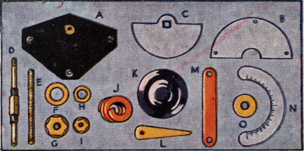
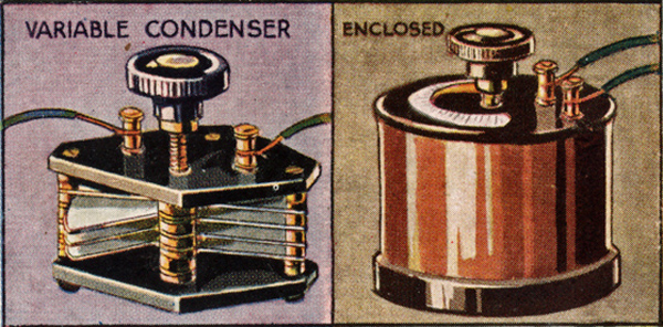
(12) The Variable Capacitor (parts).
This piece of apparatus may be made from parts supplied by wireless dealers. Parts required: 2 ebonite end plates with brass bushes (A); 4 fixed (B) and 8 moving vanes (c); 1 square spindle screwed at either end for taking the fixed vanes (D); 4 spacing washers (F); 2 nuts (G); and one small copper spring (J); 3 screwed rods for mounting fixed vanes (E); 24 nuts (H); and 9 small spacing washers (I); 1 ebonite knob (K); 1 pointer (L); 1 locking washer for securing knob (O); 1 180 degree Zylonite dial (N); 2 pieces of copper foil (M) & 2 terminals.
(13) Mounting Variable Capacitor.
The capacity of this capacitor when made up will be 0.0001 mfd (1 nF). And the illustrations show how the whole is assembled. The two strips of copper foil are connected one from a terminal to the fixed vanes, the other from the centre spindle to the other terminal. Careful assembly is necessary, and final adjustments must be made so that the rotating vanes do not touch the fixed vanes when being rotated. A section of cardboard tubing is cut so that the side of the capacitor is enclosed to keep out particles of dust which cause interference.
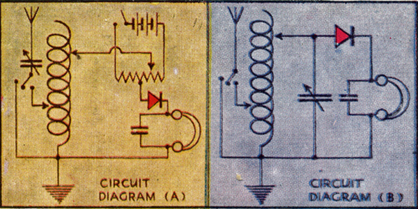
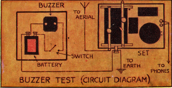
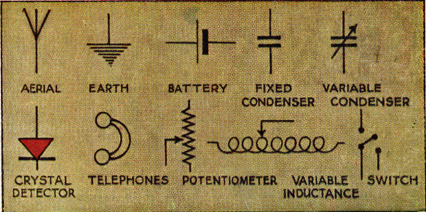
(14) Circuit Diagrams and Connecting Up.
The two diagrams show how the whole apparatus may be connected up. The one on the left indicates the connections to be made between the various pieces of apparatus when the Carborundum Detector is used. On the right we give the connections when a Perikon Detector or Wire Feeler and Crystal Detector is preferred. The variable capacitor may be connected as shown, or for experimental purposes may be placed between Aerial and inductance or in the Earth circuit as desired. Insulated bell wire, 24 gauge, will be found excellent for making connections.
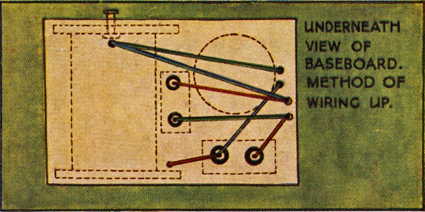
(15) Wiring Up Diagrams (underneath view).
From terminal on the front slider bar connect a wire to the crystal, also another wire from the same terminal to one side of variable capacitor.
Wires are then taken from the other side of the crystal to the headphone terminal and from the other headphone terminal to the terminal mounted on side of inductance. Also attach to this latter terminal a wire which is securely fastened to variable capacitor. Two wires are attached to the two brass nuts on either side of telephone capacitor and carried to the headphone terminal.
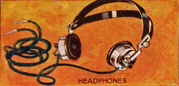
(16) Headphones.
The Telephone Receivers should be wound to not less than 4,000 Ohms, and any reputable make can be relied on.
Test For Sensitivity.
Connect one phone lead to dry battery, hold other lead with wetted finger and thumb of the right hand, and tap the remaining terminal of dry cell with wet finger of left hand. If 'phones are in good condition distinct clicks will be heard.
A FEW DON'TS - Don't drop headphones or bang earpieces. Don't look inside to 'see how they work'; they have been accurately adjusted by the makers.
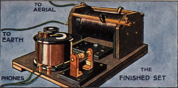
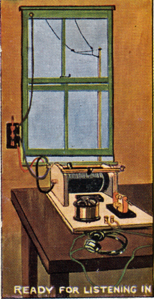
(17) The Finished Set.
Set here is illustrated with all apparatus finished mounted on baseboard and 'wired up'. The Earth and Aerial are connected up as follows: From the lead-in tube and insulated wire is taken to the terminal on the back slider bar of set, also a wire from terminal mounted on side of inductance support to the selected Earth, particulars of which are given on Card 20. Wherever connections are made to terminals, it is necessary to scrape all wires clean of insulating material.
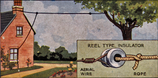
(18) The Aerial.
Aerials may be of many forms but for all practical purposes the Single Inverted L and the Twin Inverted L will be found most suitable for use with a Crystal Set. The illustration shows how the Single Inverted L should be erected. The best wire to use is 7/22 stranded copper wire. Two egg or reel shape insulators are required, and a pole or tree as far away from the house as possible up to 100 feet to which the aerial is fastened (see illustration). The secret of a good aerial is complete insulation from surrounding objects.
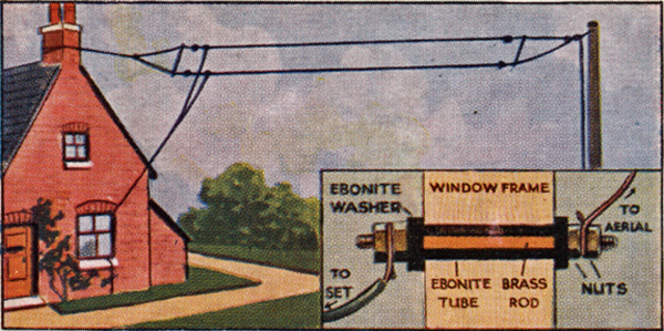
(19) The Aerial (continued).
The erection of the Twin Inverted L aerial differs little from that of the Single Inverted L, but here two wooden spreaders are required, preferably of ash or similar wood. Our illustration shows its construction quite clearly. The 'lead-in' wire is connected to a 'lead-in' tube. This consists of a piece of 2BA brass rod 8 inches long, carried inside an ebonite tube 6 inches long. On each end of the brass rod suitable terminals are attached, or four nuts and washers will answer admirably.
(20) The Earth.
This is most important in order to get good results. A stout wire, 14 or 16 gauge, is led from the set to some metal object having direct contact with the earth, such as a water supply pipe. The pipe should be carefully cleaned and a few turns of the stout wire twisted round tightly and the whole joint suitably soldered. If unavailable, an old biscuit tin or galvanised iron wire netting, buried two feet deep in a damp part of the garden, affords an excellent earth, but wire must be soldered to article buried.

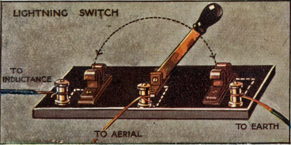
(21) The Lightening Switch.
As the aerial acts as a most efficient lightening conductor, it is advisable to connect in the circuit a switch so that in the event of atmospheric electrical disturbance the energy may be transmitted to earth and so dispersed. If a set is not so fitted, damage to the set may occur.
An ordinary tumbler switch is quite excellent, while the single-throw switch is probably cheaper and just as efficient.
Single-throw switch and method of connecting-up is illustrated.
(22) Buzzer Test.
This is used for determining the sensitive point of the crystal before reception is required. The buzzer, together with a key and dry pocket lamp battery, is mounted on a base connected up as diagram when, on depressing the key, a buzz is heard.
Method of Procedure:- Adjust headphones and depress switch with left hand. With right hand search the face of the crystal for the most sensitive point which, when found, will produce a slight buzz in the headphones. Buzzer may be connected to set or held close to inductance whichever is preferred.
(23) How to Operate Set - Perikon Detector.
Connect aerial wire to aerial terminal and earth wire to earth terminal, attach headphones to 'phone terminals and adjust comfortably to head. Bring the two crystals together carefully and explore crystal surface as explained on Card 22. Slowly advance the aerial slider across the bared inductance until the signal is heard, then slowly bring up the other slider until the greatest signal strength is obtained. The variable capacitor may now be turned from zero position until signal reaches its clearest, loudest and most effective point.
(24) How to Operate Set - Carborundum Detector.
Connect aerial and earth wires and adjust headphones as described on Card 23. Switch on current from battery to carborundum crystal detector. Advance slider as on Card 23. Move potentiometer slider and also vary pressure of steel blade on crystal until buzzer test signals become loud and clear. The actual tuning in of the station required is effected as explained on Card 23. Carborundum may not give such loud signals as some others, but it is fairly constant, Note - When not working, switch off battery to avoid wasting current.
(25) Signals and Call Signals.
With this set you should most certainly be able to pick-up your local broadcasting station if you are situated within 25 miles and are using an outside aerial. Other stations are:- North Foreland, GNF; Air Ministry, GFA; Castle Bromwich, GEC; Carnarvon, MUU; Paris, FL.
600 metres is the Universal Listening Wavelength for ships. 450 Metres is Wavelength of British DF Stations open to merchant shipping. Paris time signals are sent at 10.44 am and 10.44 pm on a Wavelength of 2,600 metres.
The reverse of all cards is printed in blue as the sample below.
|