-
Contents
(Within the text click a heading to return here)
- Electron Flow
- Space Charge
- Cathodes
- Anodes
- Grids
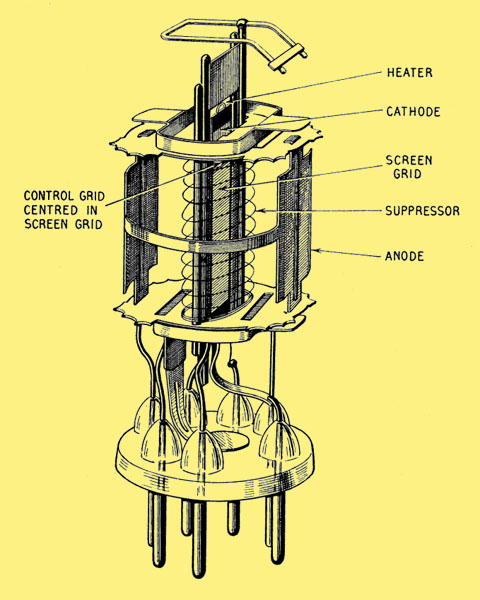
A diagram of a 'modern' or late 1940s pentode
The simplest form of the valve is the diode, which consists of two electrodes, a cathode and an anode. The two electrodes are contained in an evacuated bulb and connections are made to them through external pins or contacts. If the cathode is heated, the molecules of which the cathode is composed become increasing agitated, and if the temperature is high enough some of the electrons composing the molecules will be ejected from the cathode. This is thermionic emission.
When an electron leaves the parent molecule the latter becomes positively charged because the numbers of electrons remaining are insufficient to neutralize the positive charge in the molecule. Because the electrons are negatively charged, there is a force tending to pull them back to the cathode. The anode, which is positively charged to a higher potential, is placed near the hot cathode (usually surrounding it more or less completely) in order to attract these electrons. As they travel through the space from the cathode to the anode they may encounter molecules of gas (since the vacuum cannot be a perfect vacuum) and such collisions will impede their progress.
Consequently, the amount of gas in a valve must be as small as possible. A valve, which has been properly evacuated, is described as hard. If an appreciable quantity of gas is present, the collision between the electrons and the molecules of gas will ionise the gas and a blue haze will become visible between the electrodes; the valve is then said to be soft. Such a blue haze should not be confused with a blue glow on the inside surface of the envelope.
In travelling from the cathode to the anode, the electrons form a cloud in the intervening space, and the electric charge associated with this cloud is known as the space charge. It tends to repel the electrons leaving the cathode because it is of the same polarity, but if the potential applied to the anode is sufficiently high, the effect of the space charge will be overcome and the electrons will travel to it from the cathode, the current flow is completed through the external circuit back to the cathode. This means that there is an external electron flow from anode to cathode. In accordance with established convention, however, that the flow of electric is 'from positive to negative' i.e. in the opposite direction to electron flow, a meter will show a 'current' flowing from the positive terminal of the high-tension supply towards the anode.
As the anode potential is increased the electron flow or current will increase up to a point where the space charge is completely neutralised and the total emission of the cathode is reached. The total emission can then only be increased by increasing the temperature of the cathode.
Obviously if the anode potential is reduced to zero or is made negative, there will be no electron flow because the space charge remains un-neutralized. Hence the valve is able to conduct current in one direction only, and in fact the principal use of a diode is as a rectifier.
Although several types of cathode are used in modern valves, the differences are only in the method of producing thermionic emission. The earliest type is the bright emitter in which pure tungsten wire is heated to a temperature in the region of 2500-2600 K. At such a temperature emission of 4 to 40 mA per Watt of heating power may be obtained.
Bright emitters are still employed in high power transmitting valves for broadcasting but the only common amateur use is in diodes for applications such as noise generators. The life of a pure tungsten filament at full operating temperature is limited by evaporation of the tungsten, failure occurring when about 10% has been evaporated.
Dull emitters are directly heated thoriated tungsten cathodes which produce greater emission than bright emitters at lower temperatures and consequently require less heating power. In a dull emitter, a small quantity of thorium oxide is introduced into the pure tungsten wire, a process known as carburisation. This process creates an outer skin of tungsten carbide on the wire and facilitates the reduction of the thorium oxide to metallic thoria, stabilizes the emission and increases the surface resistance of the cathode to gas poisoning. Typical emission efficiency is in the region of 30-100 mA per Watt of heating power at an operating temperature of 1900-2100 K. This type of cathode is relatively fragile and valves should not be subjected to shocks or sharp blows.
Provided the operating temperature is correctly maintained long life may be expected. In particular, the rated voltage should be closely controlled.
Oxide coated cathodes are the most common type of thermionic emitter found in both directly and indirectly heated valves. In this type, the emissive material is usually some form of nickel ribbon, tube or thimble coated with a mixture of barium and strontium carbonate, often with a small percentage of calcium. During manufacture, the coating is reduced to its metallic form and the products of decomposition removed during the exhaustion process. The active ingredient is the barium which provides the much greater emission than thoriated tungsten at lower heating powers. Typically, 50-150 mA per Watt is obtained at temperatures of 950-1050 K.
Although the emission efficiency of oxide coated cathodes is high and large currents may be drawn, they are less able to resist the poisoning affects of gas or ion bombardment. This type must not be operated under temperature limited conditions.
An indirectly-heated cathode is a hollow metal tube or sleeve, or in some cases is of thimble shape, having a coating of emissive material on the outer surface. The cathode is heated by radiation from a metal filament, called the heater, which is mounted inside the cathode, and the heater is electrically insulated from the cathode. The emissive material is generally the same as that employed for filamentary oxide-coated cathodes and operates at about the same temperature. The cathode may be made of pure nickel or copper or of special alloys, depending upon the purpose of the valve. The heater is normally made of tungsten.
The life of valves with oxide coated cathodes is generally good provided the ratings are not exceeded. Occasionally there is some apparent reduction in anode current due to the formation of a resistance layer, between the oxide coating and the base metal, which operates as a bias resistor.
In cold cathode valves, such as gas stabilizers, the cathode is an activated metal surface.
A valve anode is generally in the form of a hollow cylinder, which surrounds the cathode and other electrodes and is intended to collect as many as possible of the electrons ejected from the cathode. In small valves the anode is made of nickel or nickel-plated steel. When it is necessary to dissipate more heat, the nickel may be carbonized to give a matt black finish and thus improve its thermal radiation. In valves with higher anode dissipations the anode must be made of a material which can operate at high temperatures such as molybdenum, carbon, tantalum or zirconium; alternatively, radiating fins are attached to the anode or the anode may form part of the external envelope of the valve and then it can be readily cooled by thermal conduction to a mass of metal forming part of an external circuit or by a circulating-water jacket or an air blast. With the aid of these cooling methods a valve of relatively small physical size can be made to handle very large amounts of power.
The electron flow from cathode to anode can be controlled in various ways and for various purposes by causing it to pass through one or more grid electrodes; in some types of valve there may be as many as four or five grids in succession. A simple system of designation has been generally adopted whereby the generic name given to a valve indicates the total number of electrodes associated with the electron flow, starting from the cathode and ending at the anode.
Grids are usually made in the form of a wire helix but are sometimes composed of square-mesh gauze. The wire helix may be of nickel or molybdenum or an alloy wound on support rods of nickel or copper, and it may be circular, oval or rectangular in section. In some VHF valves the grid is made of parallel wires tightly stretched across a hole in a disc or in the form of a squirrel cage. Many high performance valves use a form of construction known as frame grid which permits them to have a greater slope and shorter electron transit time than is possible with normal construction. One satisfactory method is to wind the grid wire under tension (about half its breaking stress) on a stiff rectangular frame to which it is firmly fixed by glazing or gold brazing. This produces a very rigid grid which can be spaced only a few thousandths of an inch from the cathode or other grids. The cathode must have a flat surface, the coating being ground flat if necessary.
In beam valves, such as cathode ray tubes, travelling wave tubes and klystrons, the grid is in the form of a single hole in a plate through which the beam passes. A voltage applied to the plate controls the beam current. This type of grid is often known as a Wehnelt.
One of the most important requirements in valve design is to prevent the grid from becoming overheated. For this purpose the grid wire may be carbonized so as to enhance the heat radiation from it and cooling fins are often attached to the support rods. In some types these rods are welded directly to conducting pins in the base which permit the heat to be transferred outside the valve. Many high performance valves employ gold or platinum-plated grids in order to avoid grid primary emission at the unavoidably high operating temperatures.
The once ubiquitous EF91, the 'model' for the diagram above