|
An Experimental Arrangement Using Very Low HT
The original term condenser is used throughout and not the modern term capacitor. 0.0005 mfd capacitors would today be referred to as 500 pF and the reaction control as 300 pF.
It is probable that many readers who delight in trying out new circuits and ideas have wanted to experiment with four-electrode valves, which are just beginning to receive quite a lot of attention, but perhaps they have not wanted to plunge straight away into the construction of a two-or three-valve set until they have mastered the essential differences between four and the ordinary three-electrode valves.
Putting it quite briefly, one of the chief advantages of the four-electrode valve is that it can be made, by suitable design, to function at least as efficiently as a three-electrode on very much lower HT voltage than is necessary for the latter. Another advantage of the four-electrode valve is that it can be made to have a very high amplification factor with a comparatively low internal AC resistance-much lower than a three-electrode valve of corresponding amplification factor would have, so that, for a given HT supply, much larger amplification is obtainable with a suitable four-elect1ode valve.
In this article the writer does not propose to go into the theory of the four-electrode valve, but simply intends to describe the construction of a single valve set which is equally suitable for short or long wavelengths (provided the tuning coil is changed, of course), and in which sufficient space has been left on the baseboard for the addition of one or even two stages of LF amplification if it is desired later to operate a loudspeaker.
The arrangement of components is quite elastic, and as the set is intended for experimental work, more controls are arranged for than are absolutely necessary. The circuit makes use of centre-tapped coils for tuning purposes, so that only one coil per range is necessary- i.e. two coils will cover the 300-500 and Daventry wavebands. It is not at all essential in this circuit for the tapping point to be exactly at the electrical centre of the coil, so that home-made coils tapped at the centre turn will do equally well.
The Circuit
There are one or two interesting points about the complete circuit shown below.
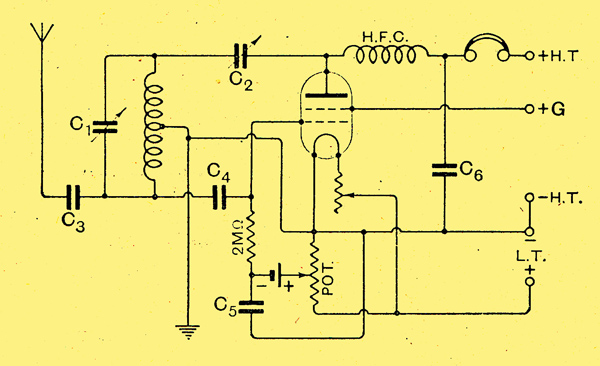
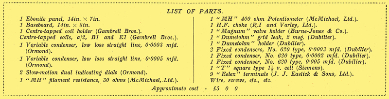
The values of the various condensers are given in the text. The coils used in the set are the Gambrell centre-tapped ones.
It may here be said that if the outer grid of the valve and the connection to the terminal marked +G were left out, the circuit would then be completely suitable for a three-electrode valve, although, of course, much higher HT values would have to be used.
The next point of interest is the use of both a potentiometer and a 1.5 Volt cell in order to control the mean grid potential. With this arrangement it is possible to change over from the anode bend to leaky grid rectification sin1ply by rotating the potentiometer knob.
The explanation of how this works is really quite simple. When the potentiometer slider is over on to the side of the potentiometer connected to negative LT, the grid of the valve is kept 1.5 Volts more negative, due to the grid bias cell. Thus for signals up to about 1 Volt (which is quite a strong signal) the grid never gets positive, so that grid current does not flow and therefore any rectification that takes place is due to the curvature of the plate current-grid volts characteristic, ie, the valve is behaving as an anode bend rectifier.
On the other hand, when the potentiometer slider is over on the positive side, which corresponds to + 2, + 4, or + 6 Volts, according to the filament voltage of the valve, and in any case is more than 1.5 Volt, the grid, or rather the end of the grid leak, will always be positive, so that most of the rectification will be of the leaky grid variety.
In this way, by using, intermediate points on the potentiometer, the most sensitive conditions for a given signal may be found. A filament resistance is also provided for, as critical adjustment of filament temperature is quite often found helpful.
Going round the circuit in detail, C1 is the main tuning condenser, about 0.0003 to 0.0005 mfd. maximum; C2 is the reaction condenser, about 0.0003 mfd. maximum; C3, is the aerial coupling condenser, which is used to reduce the damping effect of the aerial on the tuning, and for 300-2,000 metres may be about 0.0003 mfd. Mica dielectric, but for short wave work (circa 45 metres) it is advisable to use a tiny variable condenser, such as a Gambrell Neutrovernia, in this position, which may be varied to get over aerial harmonic absorption troubles (ie, dead spots where the valve will not oscillate). With this alteration, the set works well on the short waves over the whole range of the tuning condenser.
C4 is a grid condenser of about 0.0003 mfd.; C5 is not absolutely necessary, but is useful when an old, grid cell is employed, and it may have any value from about 0.002 mfd. upwards, and C6 is a small condenser of about 0.0001 to 0.0002 mid. which is rather desirable when phones are being used, so as to tie down definitely the HP potential of the end of the choke connected to the phones and so prevent the trailing leads of the latter from upsetting the tuning. It is almost essential that C1 should have a slow motion arrangement, and desirable, though not essential that C2 should have a similar arrangement. In the set described in this article both C1 and C2 are Ormond condensers with Ormond slow-motion dials, but, of course, any other well made, condenser will do equally well.
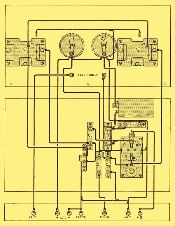
The wiring diagram. Components are lettered to correspond to the circuit.
The Valve Holder
The four-electrode valve, having one more electrode than the ordinary valve, has, therefore, to have some scheme for making connection to this extra electrode. What is usually done is to bring this lead out to a terminal on the side of the valve cap, and in the valves recommended for the set (the Aneloy AP valves See AP412P) this terminal is placed in the cap above the ordinary grid leg. To connect to this terminal a piece of flexible wire may be used, but a better arrangement is to Use a piece of springy brass or phosphor bronze with a U shaped slot cut in it and mounted on a little ebonite pillar of the right height. The photographs of the set show this arrangement, which is extremely useful because it enables the valve to be plugged-in in the usual way, thus enabling rapid change of valve be made for experimental work.
The Panel
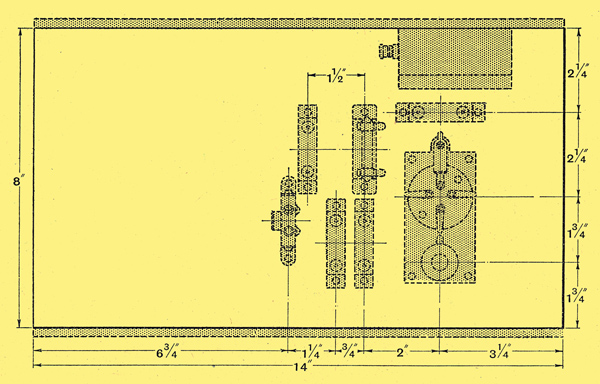
The chief dimensions and the positions of the requisite holes in the panel are shown Below.
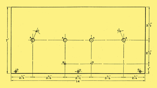
Panel dimensions. A = 3/8 in. diameter holes; B = 3/16 in. diameter holes; C = 1/8 in. diameter holes; D = 1/8 in. diameter holes, countersunk for No.4 wood screws. The 'C' holes are for securing the Ormond dials, and should be drilled at 22.5° to the vertical axis at 1 in. radius.
The Ormond dials used are made of aluminium, and serve very nicely as screens to eliminate hand capacity effects, provided they are suitably earthed. Both sides of the condenser are 'live', so that the provision of some sort of screen is essential. If the condensers are arranged as shown in the photograph, the dial fixing screws will, be found to be quite clear of the condensers, and in quite get-at-able positions for wiring.
The Ormond dials are tilted at 22.5° in the set illustrated this is quite a minor point, and need not be done if not desired, although if they are used in a normal vertical position it would be advisable to use a longer panel.
The construction of the rest of the set should not be difficult, with the aid of the baseboard layout and wiring diagram and the photographs.
The layout of the components on the baseboard. Note that room has been left for the later addition of one or two stages of LF amplification.
The Valve
See Bi-Grid exhibits
Almost any four-electrode valve will work in this circuit, though, of course, some will give much better results than others. If the reader has not a suitable valve; he is strongly advised to obtain one of the Aneloy AP valves if only for the facts that the filament consumption is so low (only 0.1 Amp at 4 Volts) and that these are the only makers supplying a complete range of four-electrode valves.
The AP412RC valve is also suitable, it has an amplification factor of about 36 to 38, and will want rather higher voltages for its most efficient functioning about 10-15 Volts on +G and either about +4 to +6 on plate or +20-30 volts. It is very interesting to experiment with +HT and +G voltages on both weak and strong signals and to find their effect on ease of oscillation.
One thing that should be noticed with this circuit is the beautifully smooth reaction control that is obtained - there is no 'banging' into oscillation and out again, and it is even difficult to tell- when the set is oscillating unless a station is being received-to tell, that is, without touching the aerial terminal to obtain the familiar double click. The tuning should be found to be extremely sharp, and any distant station must be exactly tuned in when reaction is used near its limit, or distortion will result. This tuning is quite easy with the slow-motion dials.
The set described in this article was tested at 30 miles from 2LO on an average aerial about 20 foot high, and over a dozen stations at quite reasonable telephone strength were tuned in after dusk in the course of an evening, using an AP412 HF valve and a 9 Volt grid bias battery as HT, and the set as a whole was found very nice indeed to handle.
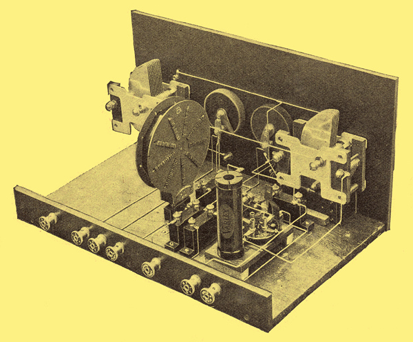
It will be seen from the photograph that the receiver Is not difficult to construct. The clip for making contact to the second grid of the valve will be noticed behind the valve holder.
|