|
Appendix
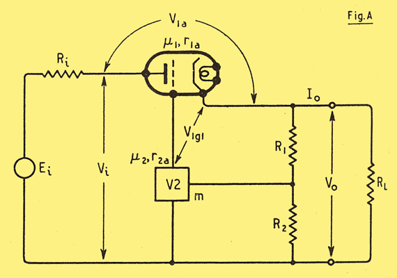
Fig. A shows the theoretical circuit of a stabilizing unit of the type considered, and Fig. B relates the quantities shown to a current/voltage diagram such as Fig. 4. Increments of these voltages and currents are denoted by the prefix Δ; and it must be borne in mind that V1a m, etc., are by no means constant, and their values must be related to the particular working points considered, while if the increments are not infinitesimal the valve parameters must be mean values.
It is assumed that the voltage and current changes are slow enough for reactance to be neglected. Of course the system could be considered more generally by substituting complex impedances for resistances. The results given here do not apply to hum, etc.
Although the sign of equality is used in all the following equations, they are subject to the approximations stated.
Part 1 Part 2 Part 3
|