|
Selections from a Designer's Notebook
Phase splitters are widely used in audio amplifiers and were treated in some detail in this journal some time ago. The notes that follow are merely disconnected jottings on a few points which, although not original, may be of interest to some readers.
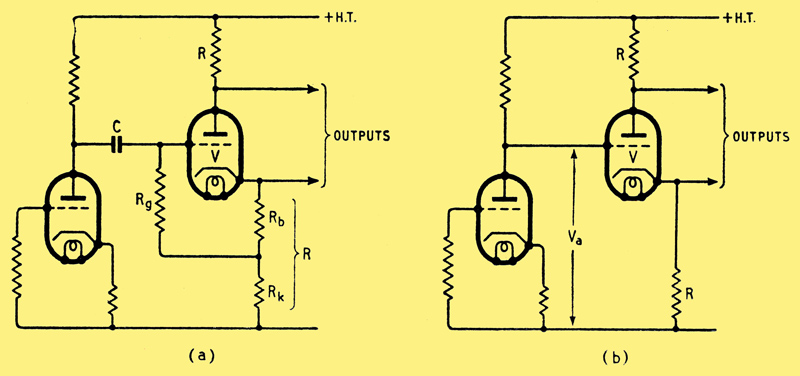
Fig. 1. 'Concertina' phase splitter: (a) AC coupled, (b) DC coupled.
One of the most widely used phase splitters is known as the 'concertina' and is shown in Fig. 1(a). In this circuit a triode, V, has equal anode and cathode loads and these are effectively in series. Consequently, any signal current in the valve passes through both resistors and so equal output signal voltages are obtained at anode and cathode. The arrangement gives a gain of little less than one (usually about 0.9) between input and either output. It has the advantage that the balance of the output voltages depends only on the maintenance of equality of anode and cathode resistors. At (a) the bias for the valve is determined by Rb which is small compared with Rk. Consequently the cathode of V is positive to earth by anything up to 100 or more volts. This being so it seems logical to couple the grid of V directly to the previous anode as shown at (b), then the cathode potential of V will be very nearly the same as the anode potential of the previous stage. Besides saving three components the coupling eliminates any phase shift at low frequencies and this is often advantageous if V is within a feedback loop, as in Mr. Williamson's amplifiers. To a sufficiently close approximation the current in V can be taken as ia = Va/R where Va is the anode potential of the previous stage. The anode-cathode voltage of V is nearly Vak = (Vb 2Va) where Vb is the supply HT potential. From this we see that it is reasonable to design for Va = Vb/3 or less. Even so, it is wise to ensure from the valve curves that no grid current flows in V even when Va is 30% more than the design figure, making due allowance for the resultant reduction of Vak. This arises because some variation in Va is to be expected with time and with valve replacement.
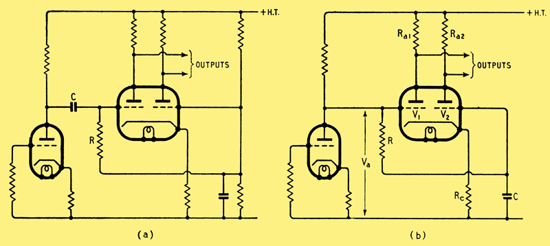
Fig. 2. Cathode-coupled phase splitter with two types of coupling.
Fig. 2(a) shows a cathode-coupled phase splitter in which the usual positive bias is supplied from a fixed potentiometer across the HT supply. A more economical arrangement is shown at (b) using fewer components, in which the positive bias is the anode potential Va of the previous stage. Both grids are obviously maintained at the same standing potential, but the signal is applied only to the grid of V, as the 'smoothing' circuit CR prevents the signal reaching the grid of V2. Similar time constants are used in the two circuits, and at medium and high frequencies the performances are identical. At very low frequencies, however, CR in circuit (a) merely leads to attenuation of both outputs, whereas (b) reverts to a push-push output of low gain as the frequency approaches zero, because the grids of V1 and V2 both follow the anode potential of the previous stage, and are in phase with one another.
An advantage of circuit (b) compared with (a) is that a large value of C can easily be used - say 2 μF or more. Such capacitors are usually of the paper-block-in-metal-can type and if used in the circuit at (a) may lead to loss at high frequencies due to the additional stray capacitance at the grid of V1. One such capacitor measured by the writer recently had a capacitor-can capacitance of more than 100 pF, and if such a capacitor is fixed to an earthed metal chassis and used as a coupling capacitor in (a), that 100 pF will appear between the grid of V1 and earth. In the circuit at (b) this capacitor-can capacitance will only add to C, and so be slightly beneficial. The circuit of Fig. 2(b) has a disadvantage inasmuch as variations in the HT supply potential may lead to a large push-push output from the splitter, and this may have undesirable results on subsequent stages.
In designing the circuit of Fig. 2(b) the anode current of V1 or V2 may be taken to be Va/2Rc and the anode-cathode potential of each valve will be Vak = Vb, Va(I + Ra/2Rc) nearly. Previous remarks concerning grid current in the circuit of Fig.1(b) apply here too.
Some designers are disinclined to use the 'concertina' and cathode-coupled circuits as both involve operating the cathode of a valve at a considerable potential to earth. A commonly used alternative is the 'see-saw' circuit. Another circuit which might be regarded as a combination of the cathode-coupled and see-saw arrangements if available, however, and is shown in Fig. 3.
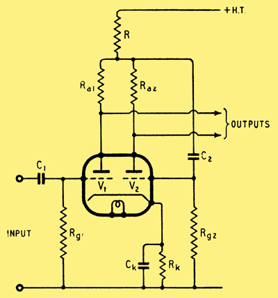
Fig. 3. Common-anode-coupled phase splitter. Typical values: V1, V2, = 6SN7, Rg1 = Rg2 = 1 mΩ, R2 = 1.8 kΩ, R = 39 kΩ, Ra1 = 80 kΩ, Ra2 = 100 kΩ, C1 = 0.05 μF, C2 = 0.25 μF, Ck = 20-50 μF, HT = 350V. Gain (input to one output) = 17 (approx.).
It will be remembered that the cathode-coupled circuit of Fig. 2 tends to maintain equality of signal currents in the two valves, and that exact equality is approached as Rc is increased, eventually becoming exact when Rc is infinite. The circuit of Fig. 3 behaves in exactly the same way, provided that we substitute R for the Rc of Fig. 2. However, in this case there must always be some signal voltage across R (to operate the grid of V2) and this signal will be in phase with that obtained from the anode of V1. Consequently, however large R may be made to achieve equality of signal currents in V1 and V2, it will always be necessary to make Ra1 less than Ra2 to obtain equality 0f output voltages. On analysis it turns out that:-
Ra1 = Ra2 (1 - (ra + Ra2 + 2R(1 + ra/Ra2) / (ra + Ra2 + (μ + 1)R)
Where μ = amplification factor; ra = AC resistance; for either of the valves.
for equal signal output voltages. In practice it is convenient to make Rk the common bias resistance for the two valves; this largely controls the direct current through the two valves and hence through R. Next, R is made as large as possible having due regard for the voltage drop across it. Ra2 is then fixed, and Ra1 calculated. The time constant C1 Rg1, is calculated as for a normal amplifier stage, and it is preferable to make C2 Rg2 several times larger than C1 Rg1 to maintain a phase displacement of 1800 between the output signals at low frequencies.
The gain from input to either output (when Ra1 is properly chosen by means of the preceding equation) is:-
A = μRa1 / (ra + Ra1 + R (Ra2 - Ra1)/(Ra2 + R))
Substitution of practical values indicates that this circuit yields a gain approaching twice that for the ordinary cathode-coupled circuit of Fig. 2 when Rc = R, and the other constants are the same in both circuits. In this respect the splitter of Fig. 3 is more like the see-saw from which a correspondingly increased gain can also be obtained, and it also suffers from the disadvantage that any disturbances on the HT line are fed preferentially to one grid, so that the arrangement should be used only with a well-smoothed supply.
In using the circuit of Fig. 3 and see-saw circuits one point needs watching. A common bias resistor is quite in order as long as it is bypassed. If it is not, then as there is feedback from both anodes to one grid, and feedback from one valve to the other via the cathode resistor, an unfortunate accidental combination of stray capacitances may easily turn either circuit into a cathode-coupled multivibrator at high frequencies. A relatively small cathode bypass capacitor will stop this trouble completely, but may also lead to a non-uniform frequency response. By using a capacitor of more usual value - 10 - 100 μF - these faults are both removed. If this is omitted and 'multivibration' takes place, the amplitude may be quite low and of quite high frequency 100 kHz or more and so difficult to find except with an oscilloscope, of low input capacitance, or a high-impedance valve voltmeter.
|