|
Money is referred to in Pounds Shillings and Pence (LSD). There were 12 Pence in a Shilling and 20 Shillings in a Pound. The UK converted to decimal currency in 1971. Five Shillings would be written as 5/- and seven Shillings and sixpence as 7/6.
The cards measure 40 mm wide and 70 mm tall.
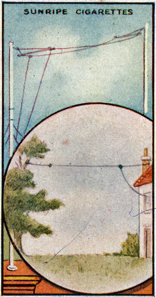 
(01) The Aerial
The aerial system of a wireless receiving station consists of an elevated wire, or wires, which collect the feeble electric waves travelling through the aether of space at a speed of 186,000 miles per second. To receive Broadcasting efficiently employ a single wire 100-ft. long and as high as possible. Keep it away from trees and large masses of metal and brickwork. A 100-ft. length of Marconi Scientific aerial wire costs 4/6.
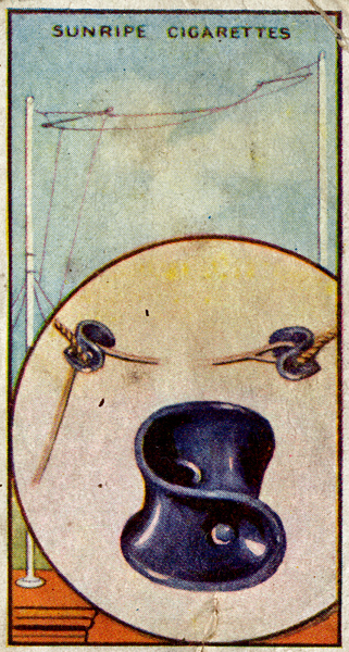
(02) Aerial Insulators
Both ends of the horizontal component of the aerial are secured to the staying ropes by means of small porcelain insulators. The Wireless currents flowing in the aerial are thus prevented from escaping to earth except via the receiving instruments. Two Marconi Scientific Aerial Insulators cost 3/-.
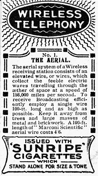
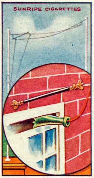
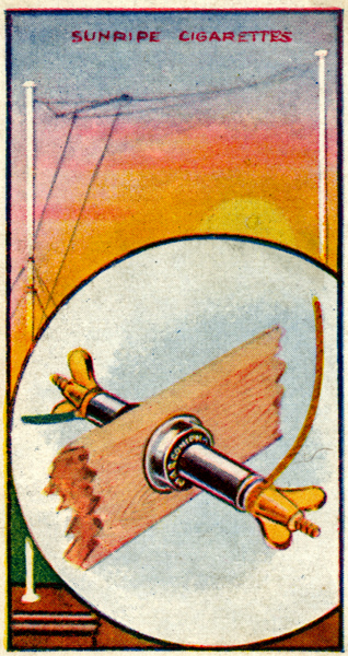
(03) Leading-in Tube
This device consists of an Ebonite Tube encasing a metal rod which terminates in butterfly clamping nuts. It serves to convey the aerial wire into the building and effectually prevents the leakage of Wireless currents. It is usually convenient to insert it in a hole drilled in a window sash. A Marconi Scientific" 12-in. Leading-in tube costs 5/-.
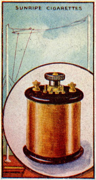
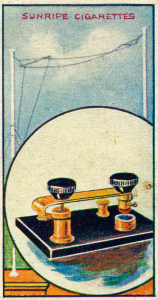
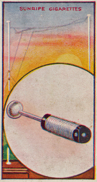
(04) Inductance Coil
This Marconi Scientific Inductance Coil is used to 'tune' the aerial, i.e. to render it responsive to Wireless waves of the particular length we desire to receive, the amount of inductance being controlled by means of the switch. The Coil, when used with a Tuning Capacitor, will enable you to receive waves having lengths between 300 and 600 metres. It costs 15/-.
(05) Tuning Capacitor
Electrical Capacitors possess the ability to store the rapidly changing currents used in Wireless Telegraphy and Telephony. Employed with the Inductance Coil shown on Card No. 4, this capacitor enables the aerial to be tuned until it is sympathetically adjusted to the wavelength of the aerial at the particular transmitting station it is desired to receive. It is of the Marconi Scientific pattern and costs #1 15s.
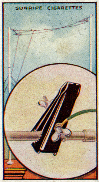
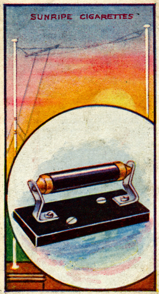
(06) The Earth Clip
The Wireless currents actuating the receiving apparatus surge from the aerial through the tuning inductance, to earth and vice versa. The apparatus is connected to earth through the medium of the Earth Clip, which should be attached to a water supply pipe. Care must be taken that the pipe is carefully cleaned at the point of connection. A Marconi Scientific Earth Clip costs 2/-.
(07) Grid Capacitor & Leak
The electric currents induced in a Wireless receiver flow first in one direction and then in the reverse. We have to cause these currents to flow in one direction only in order that the Telephone Headgear is actuated. This process, termed rectification is accomplished by using a Grid Capacitor and Leak Resistance which costs 4/6.
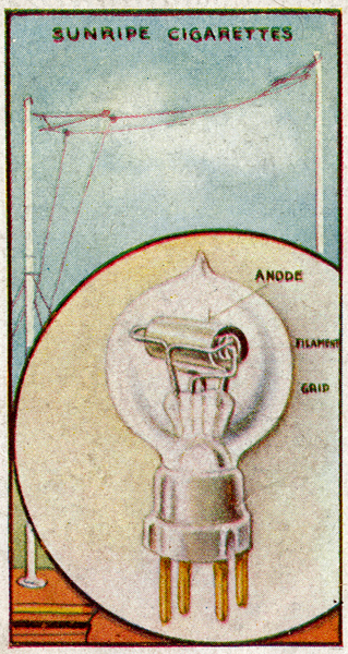
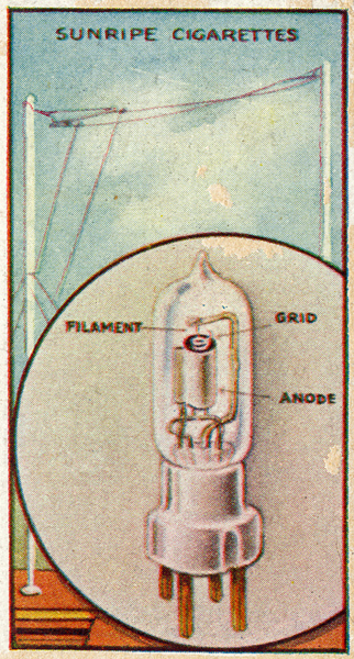
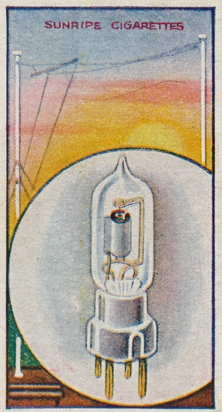
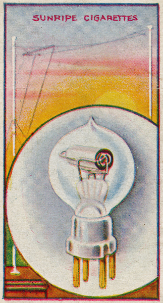
(08) Thermionic Valve
Termed The AIaddin's Lamp of Wireless this wonderful magnifying device has revolutionized the science of radio communication. It relies for its action upon the harnessing of the smallest unit of matter - the electron - of which there are millions in the compass of a pin's head. A Marconi Scientific Valve type R costs 17/6.
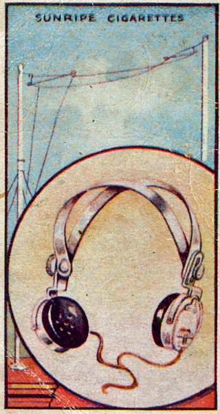
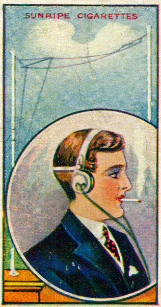
(09) Telephone Headgear
The function of the Telephone Headgear is to convert into sound the Wireless currents that have been magnified and rectified by the Valve. This type of Headgear is more sensitive than that used for wired telephony and very careful design is necessary in order that it does not produce distortion of speech and music. A pair of Marconi Scientific high-resistance Telephones costs #1 10s.
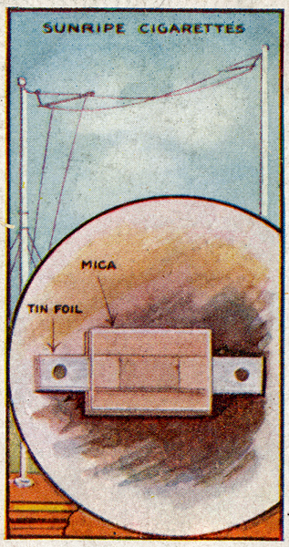
(10) Telephone Capacitor
This capacitor is connected across the Telephone Headgear, and its function is to clarify the sounds heard. It acts as a reservoir. storing the main signal and irregular currents, and discharging them in a combined even stream through the Telephone Headgear. A suitable Marconi Scientific Capacitor costs 1/-.
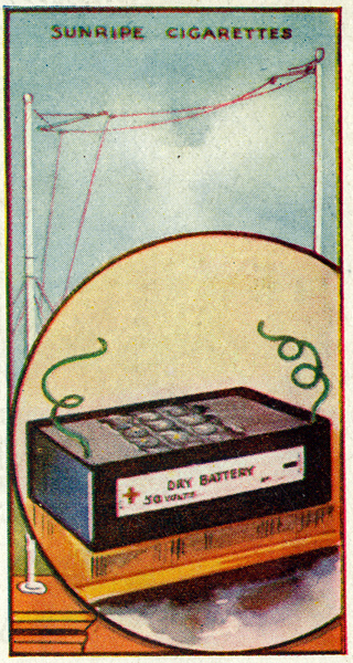
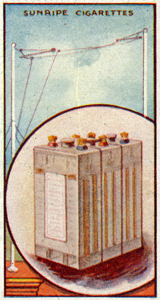
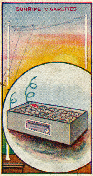
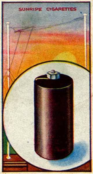
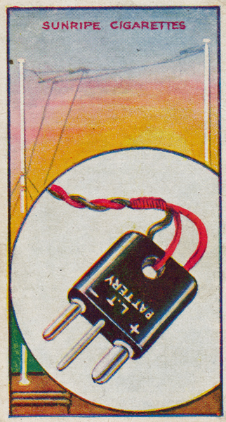
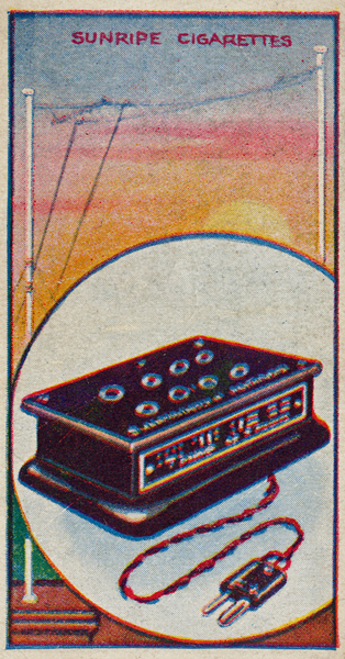
(11) High-Tension Battery
This battery supplies a small electric current at a pressure of fifty volts. Its function is to charge the anode of the valve positively in order that the negative particles of electricity emitted by the heated filament wire maybe attracted to it. Provided the battery is kept in a dry equable temperature, it will render efficient service for seven or eight months, after which it will need renewal. The Marconi Scientific pattern costs 15/-.
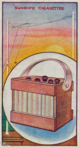
(12) Accumulator Battery
An Accumulator stores electricity which it discharges at a rate governed by its size. The Accumulator Battery heats the filament wire of the Thermionic Valve and it may be used intermittently for about fifteen hours before it requires recharging. This is effected at electrical stores and garages at a cost of a shilling or so. The Marconi Scientific type supplies current at a pressure of four volts and costs #1 3s.
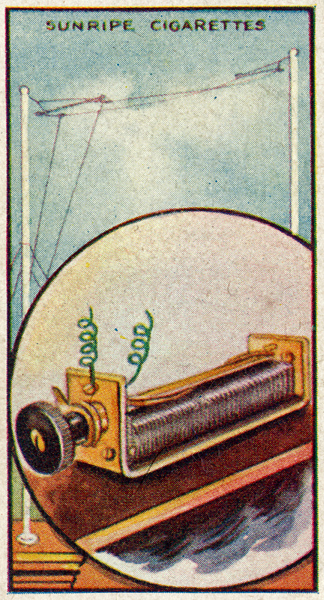
(13) Filament Rheostat
This instrument serves to regulate the amount of current supplied to the filament of the Valve by the Accumulator Battery. Since variation of the filament temperature affects the magnitude of the electron stream across the Valve, the Rheostat is able to control its sensitivity. A Marconi Scientific Filament Rheostat costs 15/-.
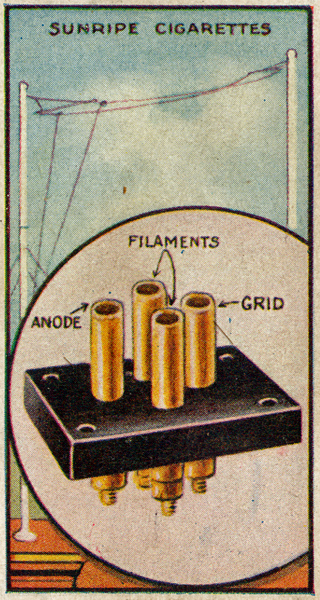
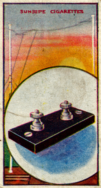
(14) The Valve Holder
This consists of a piece of ebonite into which four brass sockets are screwed. These are arranged to receive the four contact pins attached to the base of the Valve. The sockets are so disposed that it is only possible to insert the Valve in the correct way. A Marconi Scientific Valve Holder costs 1/6.
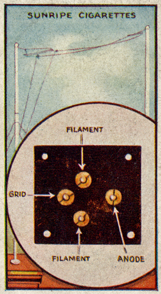
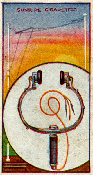
(15) Valve Holder (connecting-up)
It is important that the connections to the various sockets of the Valve Holder (card No. 14) should be carefully made. The picture shows the clamping nuts on the base. Insert the end of a length of copper wire under each nut, screw down tightly, and connect the remaining ends as shown on card No. 16.
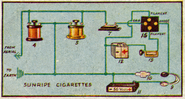
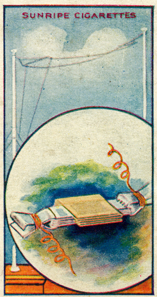
(16) Connecting Up
When the 24 cards comprising this Series have been obtained, full information is possessed regarding the construction of an efficient wireless Receiver, which has been specially designed for Messrs. R & J Hill, Ltd. by the Marconi Scientific Instrument Co., Ltd., Dollis Hill, NW. The various parts are here shown connected to-gether with insulated copper wire, the figures indicating the numbers of the relative cards.
(17) Thermionic Valve (Dull Emitter Type)
This Valve requires very little current to heat its filament. It should therefore be used in place of the R type (card 8) if accumulator charging presents dificulty. The Dry Cell, which replaces the accumulator, is dealt with on card 18. A Marconi Scientific Dull Emitter Valve costs #1 l7s. 6d.
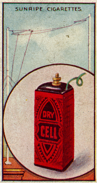
(18) Dry Cell
This Cell is used to heat the filament of the Dull Emitter Valve (card No. 17). Unlike the Accumulator, it does not require charging periodically and it will render efficient service for nine months or more, after which a new one must be purchased. A Marconi Scientific Dry Cell costs 15/-.
(19) Tuning the Receiver
When Hills Sunripe Receiver has been connected up as shown on card 16, manipulate FiIament Rheostat (card 13) until the Valve (card 8 or 17) glows brightly. Don headgear (card 9) place inductance (card 4) at Stud 1, and rotate capacitor handle (card 5). Try each stud with rotating capacitor until the required station is heard.
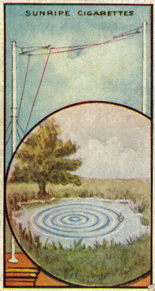
(20) Wireless Waves
Wireless communication is carried on through the medium of the all-permeating aether of space. Aether is intangible and little understood but it is helpful to conceive it as being a universal network of spiral springs which, when struck at any one point. are set into a state of general vibration. The illustration indicates another simple analogy; a stone (the transmitter) has been dropped into the pond (the aether) setting up waves which are animating the float (the receiver).
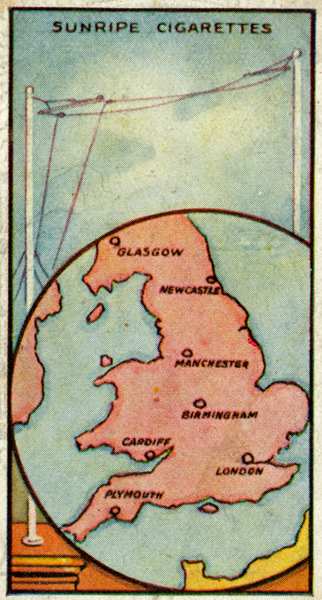
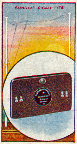
(21) Broadcasting Stations
The Marconi Scientific Instrument Co., Ltd., has designed a special Wireless Receiver for Messrs. R. & J. Hill, Ltd. the proprietors of Sunrise Cigarettes. This instrument will clearly reproduce Broadcast transmissions provided it is within 40 miles of one of the stations shown on the map. The information given in this series of 24 picture cards makes it possible to construct and operate this cheap and very efficient apparatus.
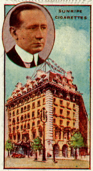
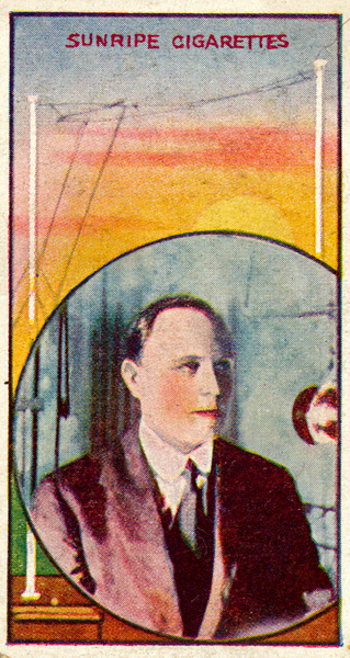
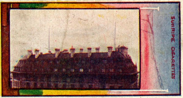
(22) Marconi House
Is the Head Office of the Marconi organization, and one of the largest commercial buildings in London. The aerial used for broadcasting can be seen suspended above the roof. The inset portrays Senatore G. Marconi, GCVO., DSc., LLD., under whose direction the Marconi System has been developed in every country in the World.
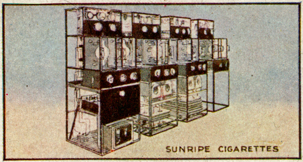
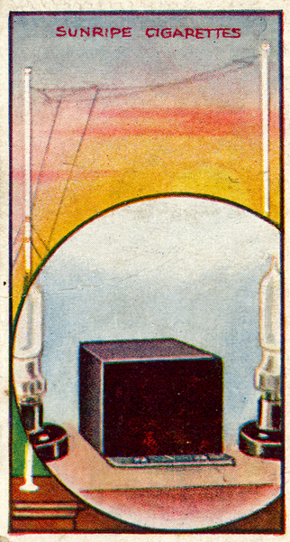
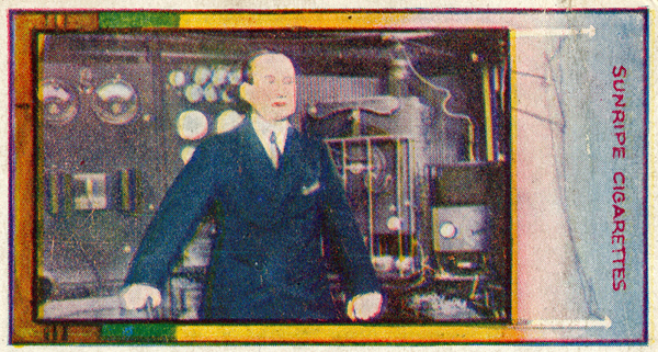
(23) The London Broadcasting Station
This station is situated at Marconi House, in the Strand, and radiates concerts, news, speeches, operas, etc., on a wavelength of 369 metres, from 5 to 10.30 pm every evening. It employs a power of 1,500 watts, the electrical equivalent of two horse-power, and has been heard as far afield as Madrid, Berlin and Christiania.
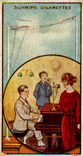
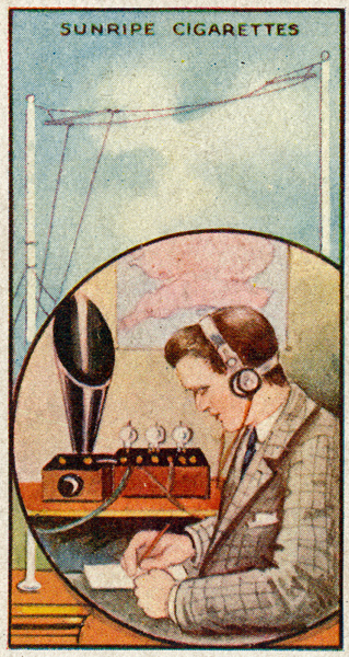
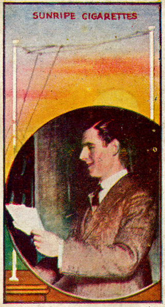
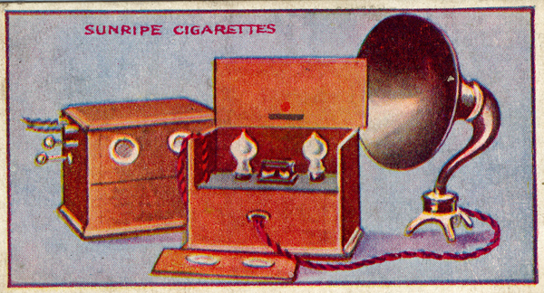
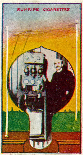
(24) A Wireless Concert
The illustration shows the transmitting studio of the London Broadcasting Station during the radiation of a Wireless concert. The artistes are seen singing into microphones which collect the sounds and transfer them in the form of electric currents to the complicated apparatus shown on Card No 23. To receive all the Broadcast transmissions it is necessary to obtain a permit from any district post office This costs 10/- and is renewable yearly.
Crystal Series
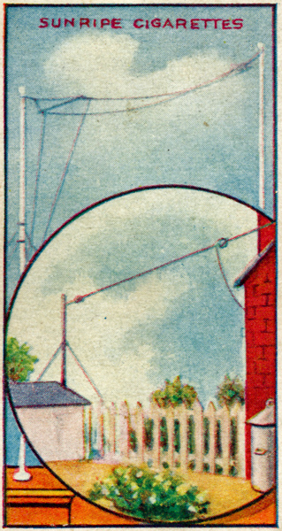
(25) The Aerial (See also card 1)
The Illustration depicts a further method of erecting the Aerial Wire. A mast is used to support the far end since no tree is available.
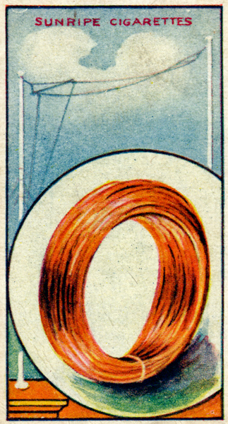
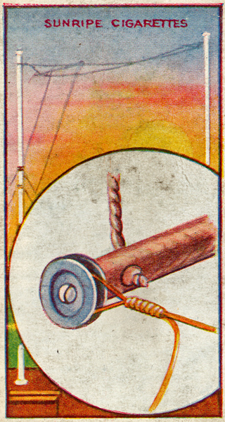
(26) Aerial Wire
Marconi Scientific Aerial Wire is composed of seven strands of No. 22 copper wire and possesses high conductivity and great mechanical strength. 100 feet is required costing 4/6.
(27) Aerial Insulators (See also card 2)
These are made of glazed porcelain. The aerial wire is fed through one hole and the stay rope through the other. Two Marconi Scientific Aerial Insulators are required, costing I/6 each.
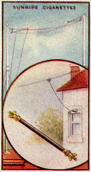
(28) Leading-in Tube
The use of this tube is explained ln Card 3. Where economy ls the major consideration a bottle neck may be employed as shown in the illustration. A Marconi Scientific Leading-in Tube costs 5/-.
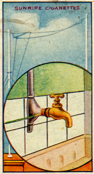
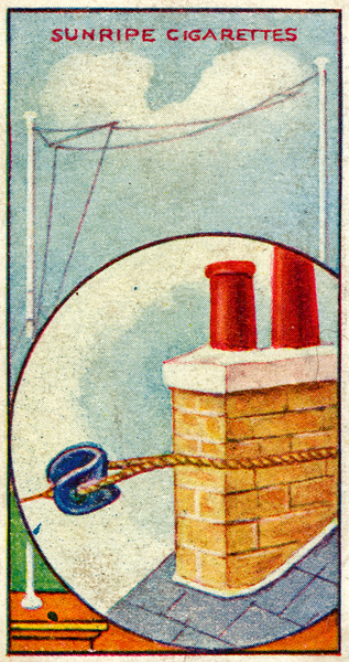
(29) The Earth Connection
If it is inconvenient to employ the earth clip dealt with on Card 6, the earthing wire should be bound round the pipe end of a water tap, both being carefully cleaned. A soldered connection should be made if possible.
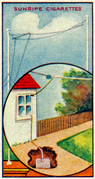
(30) The Earth Connection
In addition to the methods of earthing described on Cards 6 and 29. this illustration indicates a further scheme which should be adopted when no water pipes are close at hand. A zinc plate (2 feet 6 inches by 4 feet) is buried on edge in the ground. and the earthing wire is soldered to this.
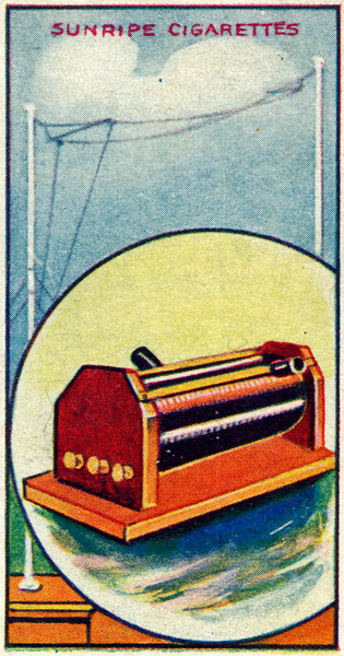
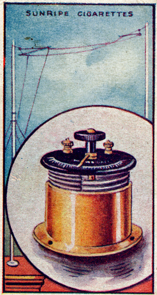
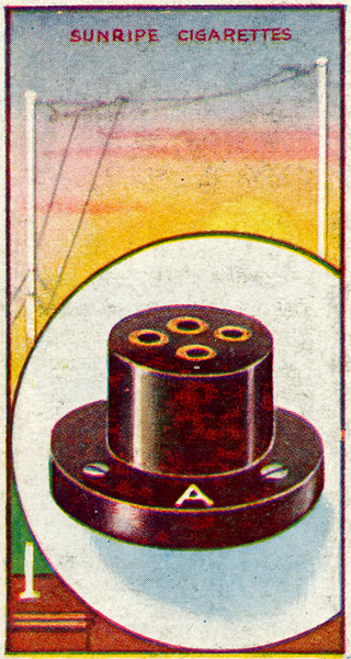
(31) The Inductance Coil
This Marconi Scientific Inductance Coil is of the double slide type, and its effect is to lengthen the aerial wire in order to render it responsive to waves of the particular length it is desired to receive. It is operative on wavelengths between 300 and 600 metres, and costs 15/-.
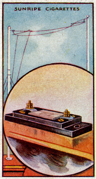
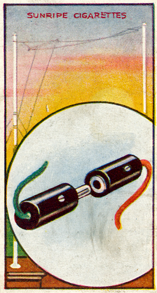
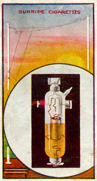
(32) The Crystal Detector
This device consists of Zincite and Bornite crystals in variable contact. It serves to convert the received wireless currents into a form in which they can actuate the Telephone Headgear and so make their presence audible. The Crystal Detector illustrated is of the Marconi Scientific pattern, and costs 7/6.
(33) Telephone Capacitor
This capacitor, which is also dealt with on Card 10, serves to impart tone to the sounds emanating from the Telephone Headgear. A tie-clip, with wire attached, may be made to grip each end for the purpose of connection. The capacitor illustrated is of the Marconi Scientific pattern, and costs 1/-
(34) Telephone Headgear (See also Card 9)
It is necessary to employ Telephone Headgear with the Crystal or Valve Receiver dealt with in this series of cards. The signals will not be sufficiently strong to actuate a Loud Speaker unless low-frequency magnifying equipment is attached. The Telephones are of the Marconi Scientific high-resistance pattern, and cost #l/I0/-
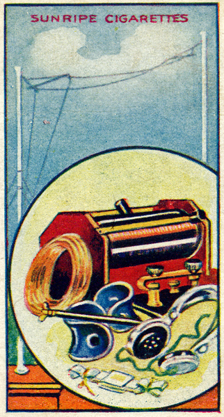
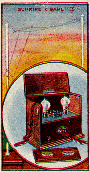
(35) Parts Necessary for the Crystal Receiver
Cards 25 to 36 (inclusive) deal with the parts necessary to build a Crystal Receiver which has been specially designed for the proprietors of Sunripe Cigarettes by The Marconi Scientific Instrument Co., Ltd. of Willesden, NWl0. This Receiver costs #3 6s., and when connected up will clearly reproduce Broadcast transmissions, provided it is within 20 miles of one of the stations shewn on Card 21.
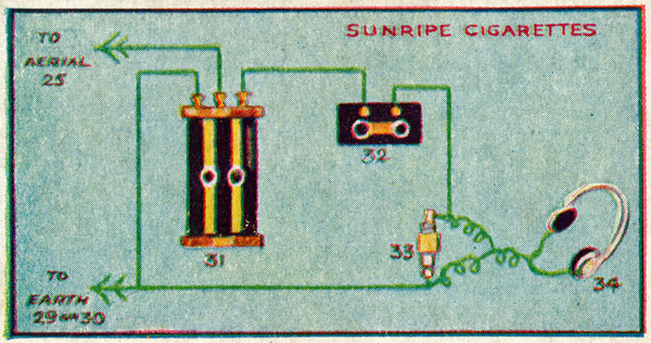
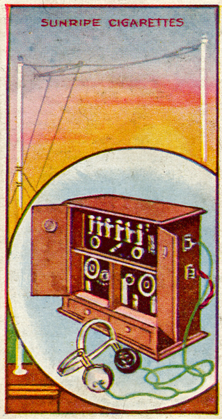
(36) Connecting up the Crystal Receiver
When Cards 25 to 36 (inclusive) have been obtained. it is possible to put together this efficient Crystal Receiver. To intercept Broadcast Telephony adjust slides and crystal contact. The parts may be obtained from The Marconi Scientific Instrument Co., Ltd., Willesden. NW10.
Marconiphone Series
(37) Valve Holder
This holder is designed to take all types of 47pin valve, such as the R. The socket marked A is the plate or anode socket and the one immediately behind is the grid socket, the remainder being the filament sockets. The sockets are so spaced that wrong connections cannot be made.
(38) The Marconi Voice Amplifier (Two Stage)
An amplifier is required for magnifying the music or speech received by the detector to a sufficient degree to operate a loud speaker (see card No. 77). The Marconiphone Voice Amplifier has been so designed as to produce this result without distortion.
(39) Aerial Spreader with Insulator Attached
This card shows the best way of fixing the aerial and down-lead to the spreader of a twin aerial. Two turns of the aerial wire should be taken round the insulator and bound with wire as shown. This obviates soldered joints.
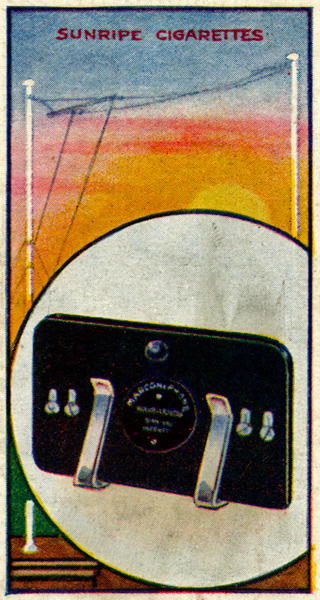
(40) Marconiphone Multi-Valve Receiver (Type RB7)
A two-circuit receiver comprising 5 high frequency valves and one detector, the valves being of the Dull Emitter type. (see card No. 53). It is designed specially for the reception from the British Broadcasting Stations. This receiver does not employ reaction, thus ensuring the utmost purity of reception.
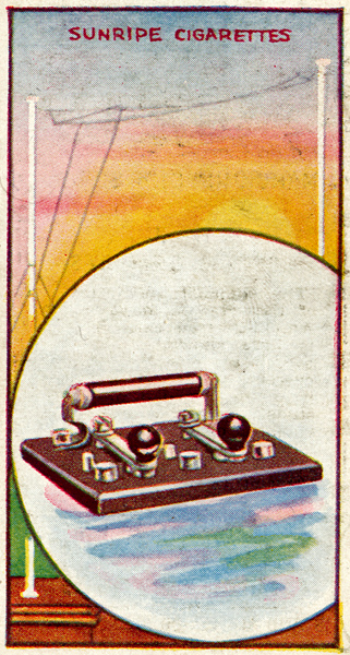
(41) Control Switches
The simplicity of operation of the Marconiphone Voice Amplifier (see card No. 38) is here shown. The left switch controls the filament current, and the right switch is placed on one of three studs, according to the volume of sound desired. The resistance shown in clips acts as a filter to remove extraneous interference.
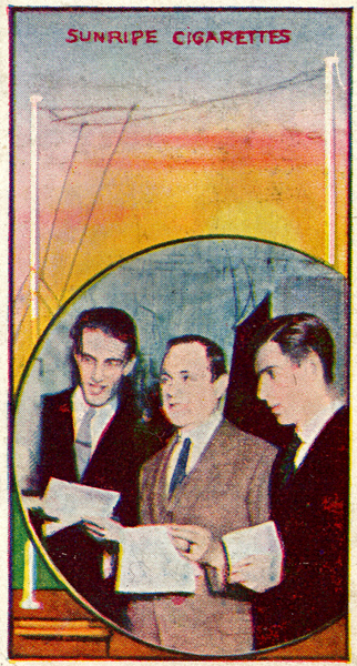
(42) A Group of Uncles
Three of the uncles at the London Station of the British Broadcasting Company. Left to right: Uncle Caractacus, Uncle Arthur & Uncle Jeff.
They are here seen talking to the children.
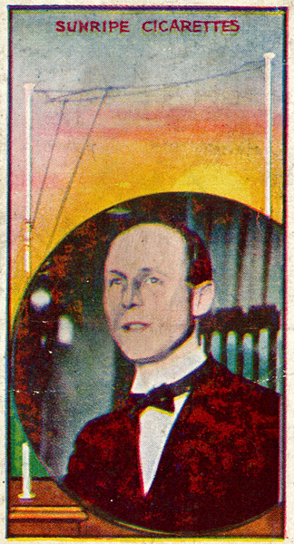
(43) Mr R F Palmer BSc (Uncle Rex)
Mr Palmer is director of the London Station of the British Broadcasting Company. He is known to children all over the country as Uncle Rex; he has an excellent voice and may sometimes be heard singing at the London Station.
(44) Mr L Stanton Jefferies (Uncle Rex)
Mr Jefferies is musical director of the London Station of the British Broadcasting Company. He is known to children all over the country as Uncle Jeff. He is here seen reading the news bulletin.
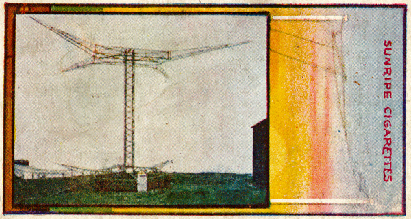
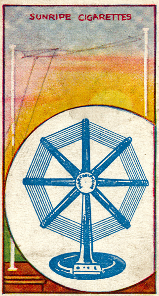
(45) Inchkeith Wireless Lighthouse
In the same way as a beam of light is sent from a lighthouse, so a wireless beam is transmitted from this station. The aerial revolves once in two minutes, and during the revolution sends out a definite Morse signal for each half-point of the compass. The transmitters are contained in the boxes shown at the base between the arms of the reflector.
(46) Marconiphone High Tension Battery
An HT Battery is the reservoir which supplies the energy required to amplify the weak impulses in the oscillatory circuit of a Valve Receiver. The positive terminal ls connected to the plate or anode of the Valve and the negative terminal to the Filament.
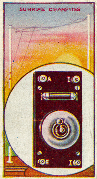
(47) Aerial and Earth Connections (Marconiphone V2)
The plug on the left is attached to the aerial down-lead and is inserted in the socket on the instrument marked Aerial. The socket on the right is attached to the earth and is placed on the plug marked Earth. Wrong connections, are thus obviated. When the set is not in use they should be joined as indicated, but this is unnecessary when using an earthing-panel. (See card No. 54.)
(48) Inter-valve Transformer
By means of this low frequency transformer the two valves of a Marconiphone V2 (see card No. 80) are enabled to give the same results as an ordinary three valve receiver. This is due to the rectified impulses from the detecting valve being transferred back to the grid of the first valve, where they are again amplified and then passed through the telephones.
(49) Mr A R Burrows (Uncle Arthur)
'The man with the voice'. Mr Burrows, whose voice is so well-known to listeners-in. is the director of programmes for the British Broadcasting Company. He is here seen speaking into a microphone at the London Station. He is known to children all over the country as Uncle Arthur.
(50) Marconiphone Frame Aerial
An extremely useful type for use when an outdoor aerial is not available, A variable capacitor should be joined across the frame in order to tune to the wavelength required. The socket on left is for outdoor aerial and the plug on right is for the earth. The centre connections are joined to the Marconiphone receiver. This arrangement allows the choice of either outdoor or Frame aerial.
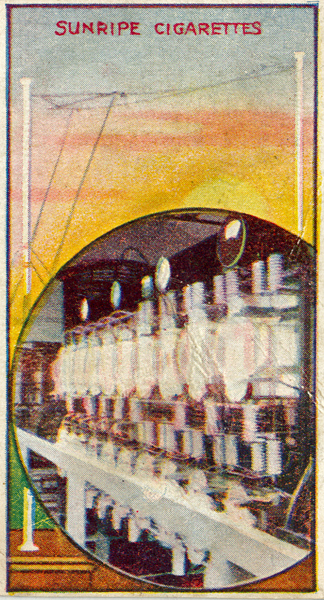
(51) 25kW Transmitter
The Marconi 25 kW station at Ongar in Essex, works at high speed to European and Canadian stations. This transmitter is heard in Java, a distance of 7,000 miles. The picture shows the valve panel of the transmitter behind which is the aerial tuning coil. Valve transmitters of this kind allow of very sharp tuning thus preventing interference.
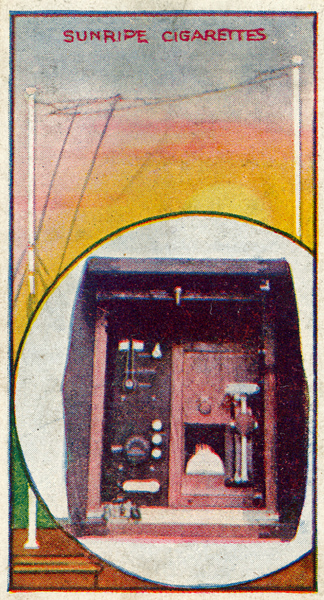
(52) A Lifeboat Wireless Set
A compact Marconi set for use in ships lifeboats. It weighs only a few pounds and has a range of about 100 miles. The quenched spark gap can be seen behind the ammeter through the glass panel. The motive power is a small petrol engine which drives a generator.
(53) Dull Emitter Valve (DEV Type)
This is a special type of low capacity valve, the filament of which has a very small current consumption owing to its being coated with a rare mineral named Thoria. The filament only requires to be run with a dull glow, thus ensuring a very long life. The filament required 3 volts and takes 0.2 Amps.
(54) Earthing Panel
This panel carries a two-way switch and should be fitted near the leading-in insulator. When the switch is 'on' the aerial is connected to the receiver, and when 'off' it is connected direct to earth, in which position it should be kept when the apparatus is not in use.
(55) Marconiphone Gramophone Adaptor
With the aid of this adaptor your gramophone can be converted into a loud speaker, All you have to do is to remove your sound box and fit in its place the Adaptor. which is connected to your receiver.
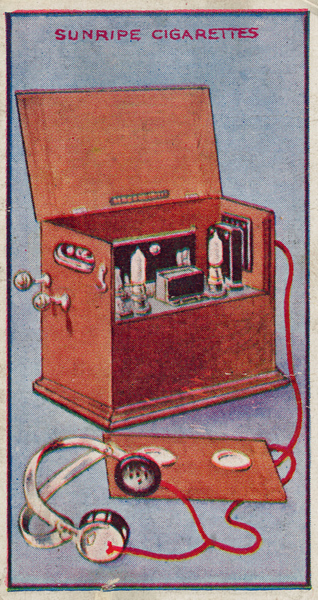
(56) Marconiphone Loudspeaking Equipment
This comprises a Marconi-phone V2 Receiver (see card No. 80) a Marconiphone Voice Amplifier (see card No. 38) and a Loud Speaker (see card No. 77).
(57) Senator G Marconi GCVO, LLD, etc.
One of the master scientists of modern times. Senator Marconi is world7famed as the man who gave us wireless telegraphy. He was born at Bologna, Italy, on April 25th, 1874. On his mother's side he of Irish descent. This photo was taken in the wireless room of the steam yacht Elettra, which plays a most important part in Senator Marconi's wireless experiments at sea.
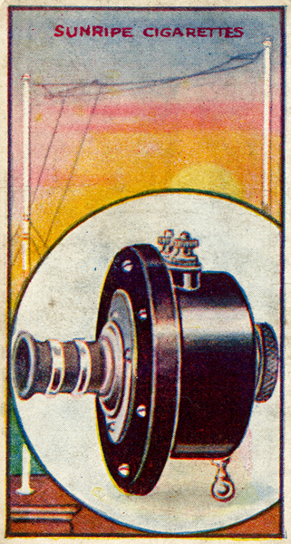
(58) Marconiphone Range Block
This consists of two specially wound coils made up on a Lessona machine. These form the aerial and plate tuning circuits of the Marconiphone V2 Receiver (see card No. 80). The alteration of the wave length of these coils is made by means of a copper 'spade' (see card No. 71). By means of a series of range blocks all wavelengths from 300 to 3.000 metres can be received.
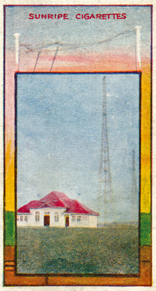
(59) A Typical Marconi Land Station
This is a 25 kW station which transmits high speed automatic telegraphy to all parts of Europe. The valve transmitting apparatus, together with the generating plant are housed in the building shown. A twin cage type aerial is suspended between the graceful 300 feet towers.
(60) Dr J A Fleming DSc, MA, FRS
Dr Fleming is widely known as the inventor of the thermionic valve which is now so largely used for wireless transmission and reception. It is the development of these valves which has enabled speech to be transmitted across the Atlantic and audiences of thousands to be entertained by broadcasting. In the photo Dr Fleming is shown with a Marconi valve transmitting set.
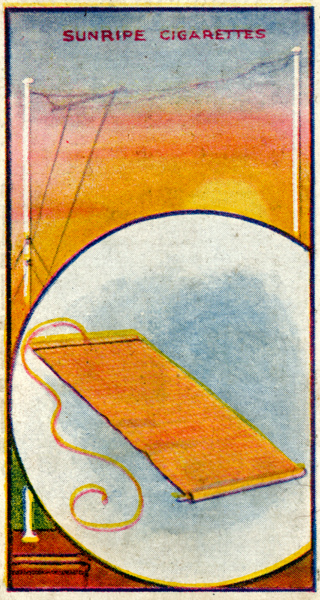
(61) Marconiphone Earth Mat
A good earth is essential for wireless reception. When it is difficult to arrange a convenient earth connection e.g. by means of a water pipe, etc.) this mat, which consists of copper gauze, laid flat on the ground or under the carpet will provide a most efficient earth. It can be rolled up when not in use.
(62) Marconiphone Lead-in Insulator
This consists of an ebonite tube, threaded on the outside, and having two ebonite nuts. Through the tube passes a metal rod having wing nuts and washers at each end. Drill a 3/4 in. hole in the window frame, slip the tube through and tighten the nuts, the leather washer being on the outside. Attach the aerial downlead and the lead from the Instrument to the respective ends.
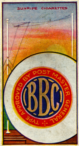
(63) BBC Symbol
All Marconiphones have this seal on them, showing that they are in accordance with the Postmaster Generals regulations, and that they can be used with the ordinary broadcasting license.

(64) The Sign of Real Quality
All Marconiphones bear this mark showing they are the product of the pioneers of Wireless Telegraphy and Telephony, and that the greatest experts in Wireless have directed their manufacture.
(65) Air Chokes
This shows one of the resistance chokes used for keeping the high frequency currents out of the low frequency circuit in the Marconiphone V2. By means of its dual amplification the two valves used in this-set perform the duties of three (see Card No. 48).
(66) Hand Telephones
A useful type of telephone especially appealing to ladies, as it does not disarrange the hair and can be used whilst wearing a hat.
(67) Range Block Clips
This card shows the method used in the Marconiphone V2 for carrying alternative range blocks (see Card No. 58). This block should be withdrawn from the holder when the receiver is in use.
(68) High Tension Terminals
This eard shows an extremely simple terminal block for attaching the connections of the high or low tension battery in order to keep them apart and so prevent them short-circuiting. They are used in the Marconiphone V2.
(69) Marconi House
The picture on this card shows Marconi House with the aerial which is used by the London Station of the British Broadcasting Company for transmitting their concerts.
(70) Grid Leak
A Grid Leak is used in conjunction with a grid capacitor to enable a valve to detect wireless telegraphy and telephony. It consists of a high resistance of 2 to 5 megohms, and allows the accumulated charge of incoming signals to leak away to the filament after the potential of the grid has been varied, instead of discharging across the valve, and thus making intermittent sounds in the telephones.
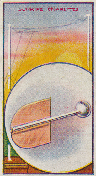
(71) Tuning Spade
Tuning of a Marconiphone is obtained by altering the position of the Spade with regard to the coils inside the Range Blocks (see card No. 58). This is effected by moving in and out the handle shown at the back of the left-hand side of the Marconiphone V2 (see card No. 80). This movement alters the value of the coil and so varies the wave length.
(72) Filament Rheostat
Is used to regulate the amount of current flowing through the filament. The type shown is that used in the Marconiphone V2, and the handle which operates it is shown in the middle of the left side of the latter. When pushed right in, the filament circuit is broken. This switches off the valves. (See Card No. 80).
(73) Marconiphone Low Tension Plug
The lead of this plug is covered with red and black braiding, The red is joined to + on accumulator and black to - (see card No. 74). The plug cannot be placed incorrectly in the LT Socket owing to its design. The centre pin prevents it being placed in the HT Battery socket.
(74) Low Tension Accumulator
This Accumulator is used for supplying the current to heat the filament of a valve in order that it can emit electrons from its surface. The illustration depicts the 6 volt 40 Amp. hour accumulator sold for use with Marconi Apparatus.
(75) Telephone Distributor
This is a heavy metal box designed to enable several pairs of phones to be used with the receiver. It has four pair of sockets into which the telephone plugs can be inserted. The plug shown in the picture is fitted into the telephone panel in place of a pair of telephones.
(76) Dull Emitter Valve (DER Type)
This is a dull burning filament valve in which the filament consumption of current is very small. It is an extremely good high frequency amplifier and detector designed for use with the valve holder shown on card No. 37. These valves are used in the Marconiphcne V2.
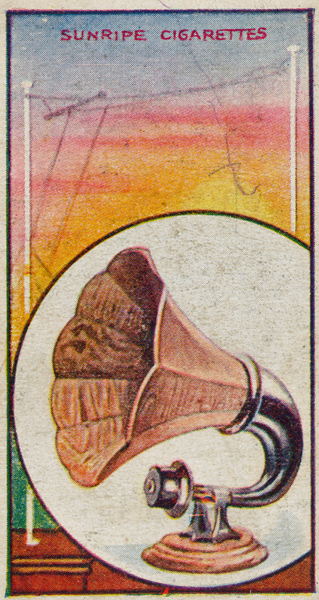
(77) Loud Speaker
This shows a typical loud speaker with polished wood horn. The base of this instrument is constructed on the same lines as a telephone earpiece but with the difference that it will carry much greater currents. These cause much heavier vibrations of the diaphragm than in the case of a telephone thus giving a much greater volume of sound which is again magnified by passing through the horn.
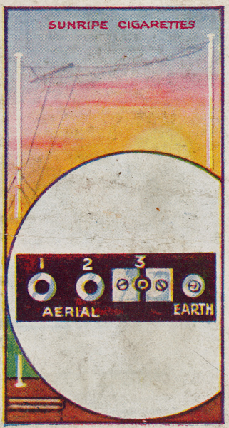
(78) Aerial & Earth Panel
This shows a special panel fitted to the left-hand side of the Marconiphoue V2 (see card No. 80), to enable it to be used with aerials of any length without employing a variable capacitor.
Socket No, 1 should be used when aerial is over 100 feet; No. 2 between 50 and 100 feet, and No. 3 when less than 50 feet. The earth connection is the same throughout.
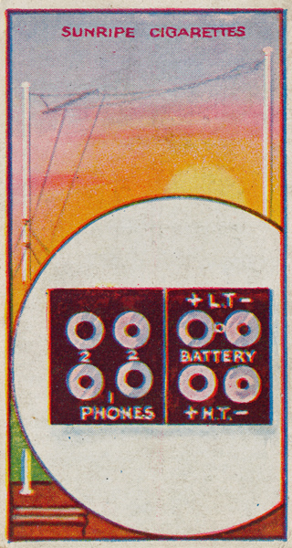
(79) Telephone & Battery Panel
This is fitted on the right hand side of the Marconiphone V2 (see card No. 80). On the left-hand side ol the panel are the Telephone sockets enabling either one or two pairs of phones to be used. On the right-hand side are the battery sockets and it is impossible to connect the batteries incorrectly owing to the special construction of the plugs and sockets.
(80) The Marconiphone V2
This Two-Valve receiver employs a special circuit by means of which the action of one valve is repeated (see Card No. 48), thus making it equal to a Three-Valve set. The necessary adjustments can be made with the utmost simplicity, no expert knowledge being required. This apparatus, with a good aerial, will receive all the British Broadcasting Stations from any part of the country.
(81) Marconi-Osram R Valve
This valve is adaptable for use either as high frequency amplifying, or detecting, or low frequency amplifying. The valve requires 4 volts on the filament and consumes about 0.67 Amps. The high tension voltage required, is between 50 and 80 volts.
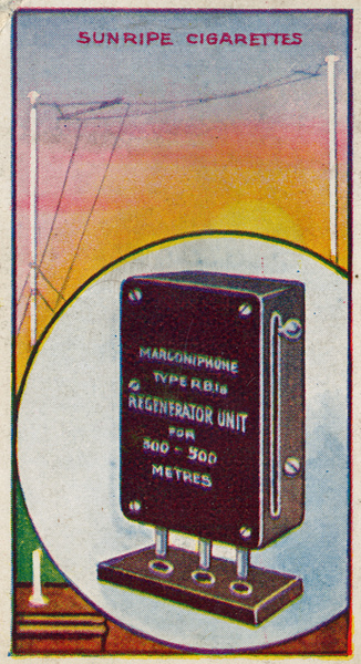
(82) Regenerator Unit
This card shows the regenerator (or reaction) unit used on the Marconiphone V2 receiver. It will be seen on the right-hand side of the instrument on Card No. 80.
This unit adds to the amplificatory powers of the receiver and enables more distant stations to be heard than in the case of a set not so fitted. It also adds to the selectiveness of the receiver.
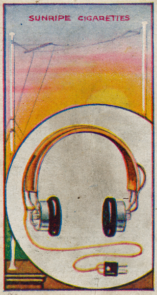
(83) Head Telephones
The current passing through the telephones causes the diaphragm contained in each earpiece to vibrate at the same. frequency as the oscillations in the aerial. which are caused by the speech or music being transmitted, thus providing faithful reproduction of the original sounds.
The type shown has a leather head-band thus being specially suitable for ladies.
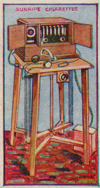
(84) Marconiphone Table De Luxe Receiver (Type RB8)
This is a two-circuit receiver comprising 5 high frequency valves and one detector.
The aerial for use with this set is situated underneath the table on which it stands, and no earth is required. The whole apparatus is therefore self contained and it can be moved from room to room in a house as desired.
|