|
A high quality audio amplifier is presented that offers advantages for the home user over the Williamson design.
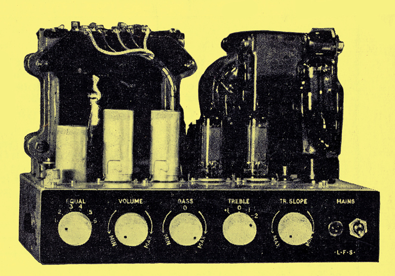
The completed amplifier
With the present (1955) availability of high quality recordings and increasing use of lightweight high fidelity pick-ups and wide range speakers, there is an understandable enthusiasm for suitable high fidelity amplifiers. Much of this originates from the very popular 'Williamson' design, which set an extremely high standard and was very widely copied in home-construction form and also commercially.
However, this particular amplifier is extremely bulky and physically generally too large for most domestic or small hall applications. Also, the high HT voltage makes the use of the standard range of electrolytic capacitors unsuitable and higher voltage, more expensive, types necessary. Another complaint common on this unit as applied to home construction is the low margin of stability; and even when these are run under normally stable conditions, exhaustive testing often reveals parasitic bursts under transient conditions and HF oscillation with capacitive loading.
It is this desirability to obtain adequate power from an amplifier of reasonably small proportions which has led to the re-introduction of the ultra-linear method of operation, and its understandable popularity. With regard to HT current drawn and power output, this method gives an efficiency roughly equal to pentode conditions. The maximum output is also similar to pentodes. Distortion for a given output level is lower than either pentodes or triodes. Output impedance, an important factor in ensuring good speaker damping, is very much less than for pentodes and only a little higher than triodes. Linearity is also very good. All this is not achieved without loss; as the local feedback brought about by the screen tap requires slightly extra grid voltage drive over pentodes, but this is not unduly difficult to allow for in the amplifier design, Therefore, to obtain results at least comparable with triodes it is possible to make an amplifier either give more output, when using the original valves in the new arrangement, or to make an equivalent amplifier output with smaller valves and lower HT supplies. For normal use the latter arrangement is by far the more satisfactory, as it then allows the use of smaller and cheaper components (more conservatively rated) and a reduction in physical size, consumption and overall cost.
The American designers, Hafler and Keroes, who made this type circuit so popular, specify that for KT66 type valves the ratio of winding for the screen tap should be 43% for optimum results, but in Britain the published data would indicate that about 20-25% would be more suitable. However, most of the high quality output transformers produced here commercially for this application adhere to the American specification although this may, of course, be done to satisfy the export market.
For 6V6 operation these same designers specify that the optimum tap ratio is 24%.
For the amplifier design given here type 6BW6 valves are used, as these are noval (B9A) based versions of the 6V6 and electrically identical. With a mains transformer of 300/0/300 V secondary this gives an HT line of around 330 Volts; a figure which allows standard type electrolytics to be used for smoothing. The reservoir fitted was a paper type, as this was handy, and allowed better reliability, but it can be replaced by an equivalent capacity plain foil electrolytic of about 450/500 Volts working. Although miniature valves are used throughout, the rectifier is a standard octal type in order to give very conservative current rating and to ensure adequate continuous sine wave power output and good high power transient response. Under these conditions the amplifier gives over 10 Watts continuous sine wave output (this being the actual power measured into a resistor load of 15 Ohms). In the region 20-20,000 Hz the output is around 10-12 Watts at low distortion. At the high frequency end distortion is just perceivable on a scope at 7.5 Watts at 50 kHz. At the low end this occurs at 15 cycles at 8.8 W. Beyond these points the output handling capability drops off fairly rapidly, but in any case these are beyond the limits of the recordings and their associated pick-ups. The tone controls are also determined to give a limit to the frequency response. This excellent low frequency power handling is due to the very generous core size of the output transformer.
Frequency Response
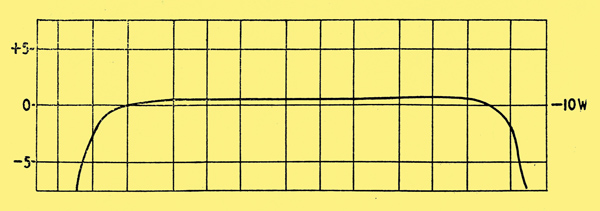
Power response into 15Ω resistor
The curves are shown for this at a reference level of 5V into a 15Ω resistor load, this being a probable average mean level of music or similar signal. The input signal source consisted of a sine wave oscillator of constant amplitude covering the range 5.5 to 70 kHz. The input was injected into the main amplifier with the specified 18db of feedback.
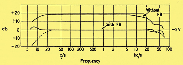
Response characteristics. The dotted lines indicate response from PU input (tone controls set to flat)
Even without feedback the frequency response is reasonably flat over the entire audio range, so that the amount of feedback is fairly constant in this range and maintains the low output impedance, low distortion, etc., well beyond the limits of any speaker into which it will feed. It was felt very desirable to maintain a high damping factor over as wide a range as possible in order to obtain optimum speaker performance.
With reference to the mid-frequency level, the output rises approximately 3db at 8 Hz and falls back to zero level at 6 Hz. At the high end, the level rises approximately 0.5db at 30 kHz, falls to minus 2db at 36 kHz, and rises again slightly to a minus 1db condition at 54 kHz. Beyond this the response falls again and is some 3db down at 70 kHz. It is presumed that it continues to drop further after this point, but this was the limit of the test equipment. The slight rise at low frequency and the slight kink before the fall at high frequency are general characteristics of feedback amplifiers, and similar deviations occur in the Williamson and other similar units. However, these deviations are not of any significant amplitude and are outside the frequency range set by other requirements.
At low frequencies there is a tendency to reproduce turntable rumble if the response is extended too far, so that the time constants of the tone circuits and the pre-amplifier stage are set to give some degree of attenuation at these very low frequencies, thus they do not enter the main amplifier to any extent and the slight hump at 8 Hz assumes no significance. The tone circuits and pre-amplifier constants also give a gentle fall at the high frequency end. With the input into the pick-up socket, tone controls set to fiat, and volume control approximately half-way, the response falls 3db at 32 kHZ - 4db at 50 kHz and 9db at 70 kHz. This easily satisfies the required response. These are the measurements at the 'flat' setting, and a considerable plus and minus variation is possible at various settings of the tone controls, both at low and high frequency ends.
Stability
This is usually the bugbear of feedback amplifiers, and often the margin existing is too low to maintain absolute trouble free conditions under a wide variation of input signals (particularly transients). Also, the necessities of home construction often mean that there are very minor changes in layout and possibly component specification. Most people have the sense to adhere strictly to the output transformer specification, but there is often a great deal of variation in transformers made commercially, even though they are supposedly to the same specification. It is quite common for a specific amplifier to work satisfactorily with one make of transformer, and not with another made by a different manufacturer advertised as to the same requirements. Therefore a great deal of time was spent in very severe stability testing, and although the precautions taken and the tests themselves might possibly be regarded as over-elaborate in that they allow for conditions almost impossible to occur in practice (unless done deliberately), they do, in fact, ensure an adequate stability margin under any normal conditions.
- The output valves chosen are of lower slope than those often used for this type of output stage, and are less likely to suffer from parasitics. As an added safeguard, grid and screen stoppers are fitted at the valve pins.
- Although only 18db of feedback is used, and this is ample in obtaining optimum output conditions, the correction was set to allow a much greater amount. On test it was found that the feedback resistor could be reduced to a condition of over 30db of feedback before the amplifier developed HF oscillation, so that an ample gain margin exists.
- As a loudspeaker impedance rises very considerably at some frequencies (particularly when not ideally matched to a cabinet), many experiments were tried with other load resistances and also with an open circuit load as well as speaker loading. Also, various capacities were paralleled with the various loads to determine the maximum capacity loading permissible under widely differing load conditions. Most of the effect of capacity loading is to produce HF oscillation at higher capacity values. As the speaker coil looks like an HF choke at these frequencies, these tests can be simulated with a suitable choke. In fact, although speaker and choke were tried, the results under open circuit conditions and with pure capacitive load only, are so similar that this simple test is advised. It was found that under these conditions a resistor across the output raised the value of capacity necessary for HF oscillation to commence. This resistor was therefore fitted, even though the amplifier is completely stable without it, as it only absorbs some 2 or 3% of the power output and yet increases the stability against capacitive loading by a considerably greater amount. These tests were also carried out under square wave conditions
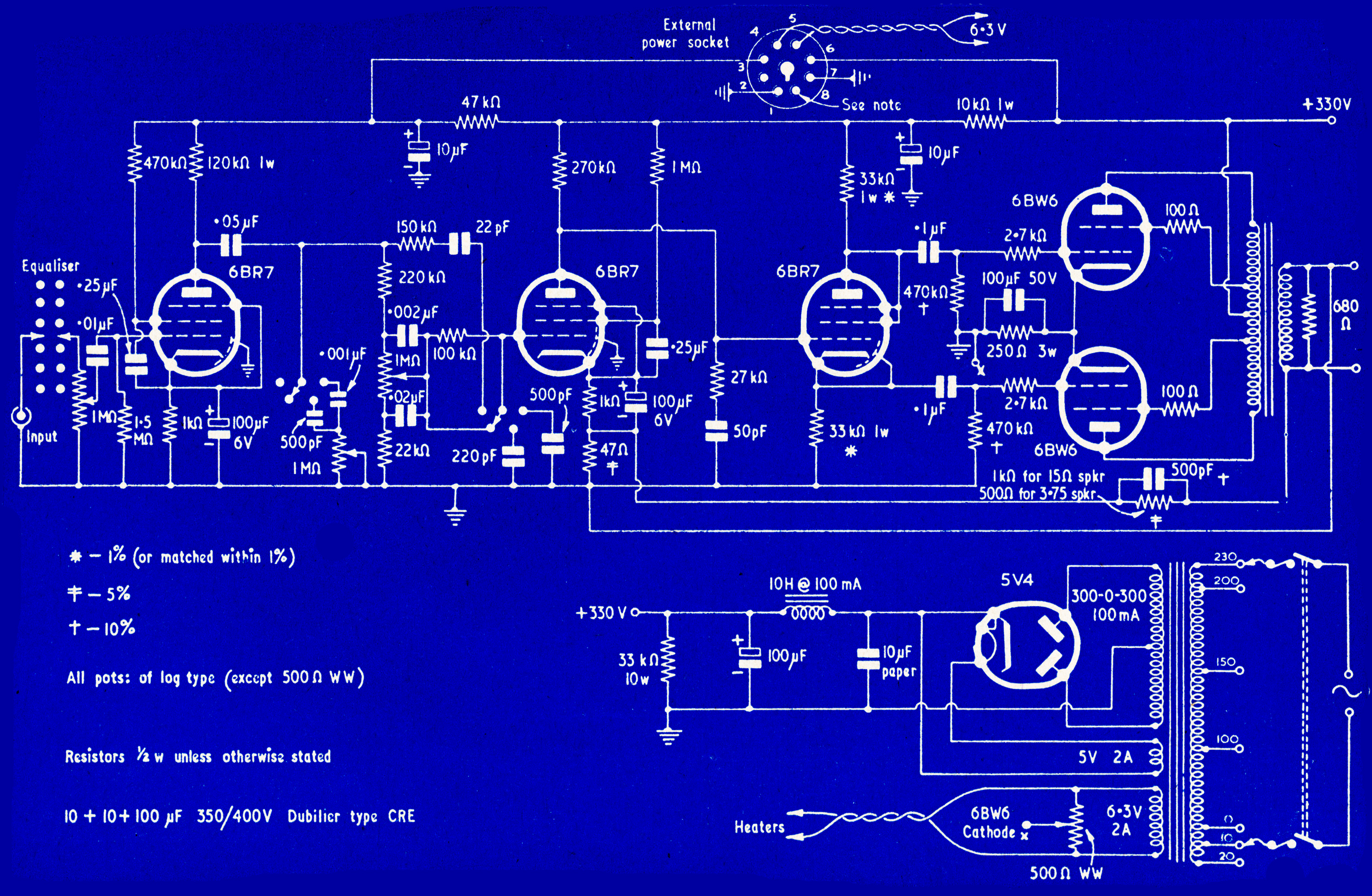
Circuit
Note: the heater tap X should be connected to the cathode side of the 250Ω 3 W resistor.
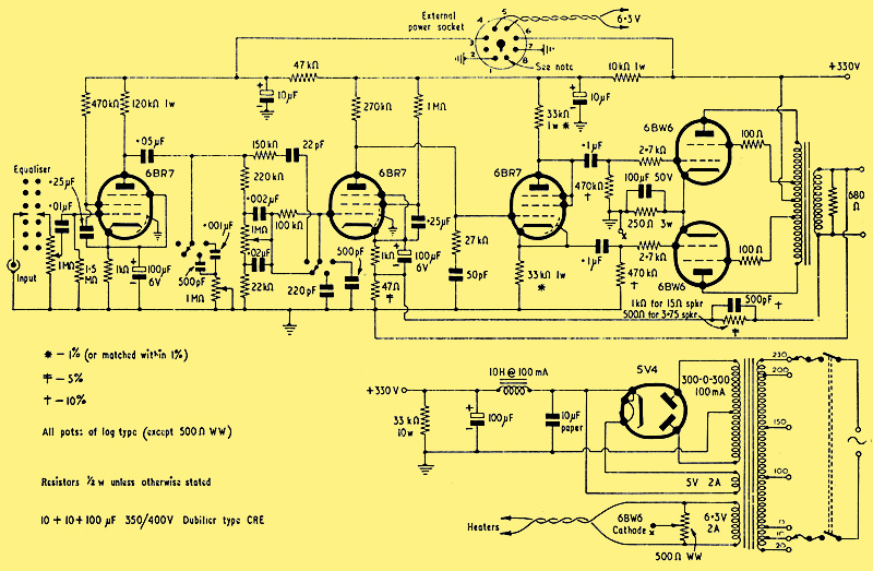
Circuit Diagram. Click for full size 'blueprint'
Valves used: 6BR7 x 3, 6BW6 x 2 & 5V4.
Primarily the amplifier was designed to work with crystal pick-ups of transcription quality (Collaro Studio P etc.) and it is possible that the use of high quality dynamic pick-ups would give insufficient output to fully drive the amplifier; particularly as these require rather more correction. However, a suitable head amplifier could be made as an extension, and an octal socket is provided at the rear of the unit in order to take off the power supply for this and similar purposes.
Following the input socket is a 6-way 2-pole switch, and this is arranged to bring in suitable equalisers for the particular type of pick-up, recording, tuner, etc., in use. Values are given for certain popular pick-ups for 78 rpm and LP records. Other values will be dependent on the pick-up and can be obtained from the maker. Some amplifiers use a plug-in type of equaliser, but this could mean sorting out the appropriate plug and fiddling round the back of the amplifier, even to change from 78 rpm to LP and vice versa. A switch was considered to be much more convenient.
Following the equaliser and the pre-amplifier are the tone control circuits. No originality is claimed for these, as they are similar to those used in the Osram 912. These give a range of control which covers almost every requirement, so that there is no point in spending time in making up a different circuit to achieve similar results.
The output from the tone control circuits feeds into the main amplifier. The first stage of this is a voltage amplifier. A pentode was chosen as it gives a greater undistorted output swing, and this is necessary due to the lower slope and larger grid swing of the output valves. It was felt desirable, also, to reduce the phase shift within the feedback loop as much as possible, and to this end the first stage is directly coupled to the phase splitter.
This puts some complication into the design of the first stage, in that it must work at an anode voltage which is necessary for correct conditions in the phase splitter stage. However, after some tests with an audio oscillator and a scope, component values were determined which give more than adequate output voltage without waveform distortion. The feedback is introduced into the cathode of this valve, and its high stage gain also allows ample feedback without undue loss of sensitivity. At the anode of this stage is connected a phase correction network. Although the phase splitter is in fact a triode and would not normally provide ample voltage swing under the usual conditions to fully drive the output valves, the large stage feedback of the un-bypassed cathode resistor reduces any distortion that might have been introduced internally in this stage to negligible proportions. After the phase splitter come the output valves. As in the rest of the main amplifier, the time constants have been kept rather long; also, the cathode resistor is common to both valves so that the response at low frequencies is improved over the condition when separate bias is used. This can be readily shown on a low frequency square wave test. Although, strictly speaking, the cathode bypass capacitor could possibly be omitted, this is included in order to give improved response at high level transients.
The heart of any feedback amplifier is, of course, the output transformer. A large core area was used and this was designed to give a primary inductance of greater than 80 H at 5V, 50 Hz, with low leakage inductance and output impedances most adaptable for general use.
It has been shown in leakage inductance charts that for a given number of windings the best coupling is achieved when the outer sections are about half the size of the inner ones. In this particular unit the two primary halves are cross-coupled with roughly this ratio of distribution. Suitably interspersed are the four secondary windings, so that there is tight coupling both between primary halves and also between primary and secondary. Winding details and connections are given below.
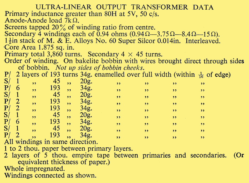
The original transformer was, in fact, wound by hand, using only a hand drill clamped in a vice. The only deviation in the data, compared with the original, is that a few extra turns have been added, as the original was rather close to the inductance figure and this addition allows a more ample margin. Inductance should be checked by measuring the AC through the whole primary with 5 V, 50 Hz applied (it should be 200 μA or less). The fact that the winding is wound right across the bobbin, instead of in two separate side-by-side bobbins, makes it much easier to wind. As the primaries are inter-coupled this evens out the DC resistance so that the resistances of the two halves are almost identical.
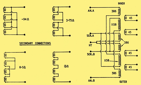
Output Transformer Winding Details
It is essential for optimum performance that all the windings of the secondary be in use, and various ways of connecting them to obtain differing output impedances are shown. The 3.75Ω and 15Ω conditions are best. For 15Ω the feedback resistor should be 1,000Ω and for 3.75Ω output the feedback resistor should be 500Ω. Ideally, the capacitor in the feedback path should be increased to 1,000 pF in the 3.75Ω condition, but this can be left at 500 pF for both.
Commercial Output Transformers
There are available several commercial output transformers for ultra-linear use which have the correct impedances; primary to secondary ratio and primary tap ratio. However, many of these have insufficient primary inductance to meet the specification of this particular amplifier. Of the ones which might be suitable, that made by R F Gilson Ltd. (type WO7l0) was tested, as this is also of very reasonable price and should therefore appeal to those who would rather buy the ready-made product. This unit is not wound to the winding data given but to the manufacturers design. Outwardly it would appear to be extremely small in comparison, but the laminations are of grain orientated material, so that over most of the range the performance is the same.
The frequency response was found to be almost identical. Power handling over most of the range, including the high frequency end, is quite adequate. At the low frequency it falls off a little before its larger counterpart due to the core size, but the low frequency power handling is ample for any speakers which would be normally used. The transformer will allow a somewhat better margin of negative feedback, but has somewhat less discrimination against capacitive loading. However, these tests were far worse than would normally appear in practice, so that the WO710 should be quite suitable. No trouble was experienced with its use under normal conditions. The output windings are actually two windings of 3.7Ω giving either a (parallel) output of 3.7Ω or (series) output of 15Ω. These two impedances cover most of the speakers which would be used.
Construction
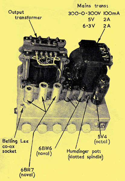
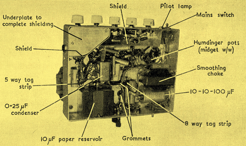
Component layout - top view
The amplifier was constructed on an aluminium chassis l0.5 x 8 x 2.25 inches with welded corners. This includes all the circuit; the tone controls, on/off switch and indicator lamp all being mounted on the front under the chassis. Almost half the top area of the chassis is taken up by the mains transformer and output transformer, the valves being in single file in front of these. All other components are fitted under the chassis, The layout shown should be copied in order to reduce stray pick-up.
Component layout - under chassis view
The pre-amplifier valve has a PTF. holder mounted on rubber grommets, but this valve is of anti-microphonic design and so it may be possible to eliminate this precaution. The valve has a steel can to reduce electrostatic and electromagnetic fields, and the base is boxed in by separate shielding. This extends across the base, with the anode side protruding, and also encloses the equaliser circuits and the volume control. A shield also extends behind the tone controls up to the 0.25 μF screen by-pass capacitors. These are mounted in 'double decker' fashion and in turn provide an extension of the shielding, so that all the input stages are shielded from the phase splitter and output valves. The remaining 6BR7s are also fitted with cans. This virtually rules out the possibility of any feedback due to stray couplings. The actual signal wiring is carried out by mounting the components close to the valve bases to keep the wiring as short and direct as possible. The heater wiring is in twisted pair, close to the holders, but it should be kept away from the pre-amplifier grid circuits. The additional shielding already mentioned on this stage makes this point relatively easy. All the other circuits, such as HT feeds and connections to by-passed points, are run in cable form and laced up, as all these leads are 'dead' as regards to signal.
To combat hum, no heater current flows through the chassis. Also, as there is a fairly high alternating current flowing into the reservoir capacitor, the earth of the transformer HT winding is returned direct to the earth connection of the reservoir; then to chassis. This cuts out the charge current flowing through the chassis.
Apart from the output transformer, all the items should be easily obtainable from reputable dealers. Do not be tempted to use cheap components, as they often result in failure and cause valve or other breakdowns which are certainly not cheap. All coupling capacitors are of the paper type hermetically sealed in aluminium tubes. Small values are either mica or ceramic types of adequate working voltage. The screen bypass capacitors were Dubilier 'Nitrogol' block type, but these can be of a similar type to the coupling capacitors. The HT electrolytic is a 10-10-100 μF 350/400 V Dubilier 'Drilitic' type CRE.
Panel
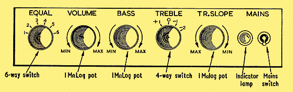
Front Panel
The control panel was engraved in laminated black plastic (white letters on a black ground) and gives a professional finish to the amplifier.
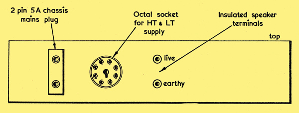
Rear Panel
Miscellaneous Data
Input into PU socket for 10 W output, 87 mV. Input into PU socket for 1 W output, 27.5 mV.
Controls at 'Flat'
With no load connected: amplifier is stable with 0.06 μF or less across output terminals. HF bursts occur when capacity is 0.07 μF or over.
With 47Ω load, capacity must be > 0.75 μF for HF oscillation.
With 15Ω load, capacities up to 24 μF (paper) tried. No effect.
Octal Socket Connections
- Earth
- No connection
- HT supply to pre-amplifier valve
- 6.3 V AC heater supply
- 6.3 V AC heater supply
- 330 V smoothed HT
- Earth
- Signal input (co-ax, to equaliser Pos 6).
Tone Controls
All controls are 'flat' at 0 position
Bass ±13db at 50 Hz
Treble position +1. +5.5db at 10 kHz.
Treble position -1. -12.5db at 10 kHz.
Maximum slope
Treble position -2. -26db at 10 kHz.
Negative feedback: approx 18db.
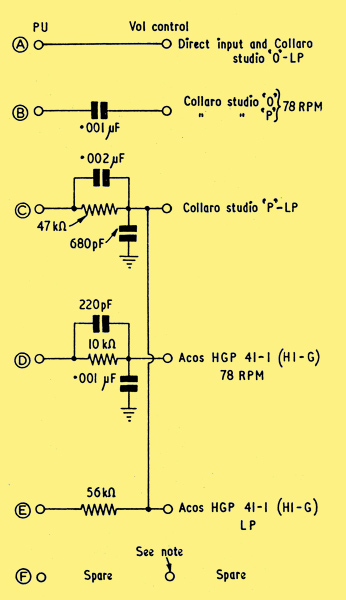
Suggested Equaliser Circuit
It is suggested that the volume control side of the 'spare' switch position should be connected by screened cable to pin 8 of the octal power socket, enabling this to be used as an 'external unit' position.
|