|
This little amplifier has many applications, these ranging from standard workshop use to amplification of radios. Both circuit and construction are simple, and the article also gives details of a suitable cabinet in which the amplifier and its speaker may be housed.
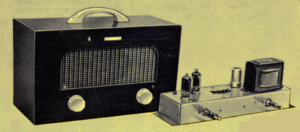
This is a simple little amplifier which was built originally for service on the workshop bench, and for amplifying portable music players (in the 1960s these were small transistor radios). In this service it earned a great deal of popularity. Construction is quite simple and can be undertaken with confidence by anyone having an elementary knowledge of the subject and a small soldering iron. The components are few, and many readers will no doubt find all they want in the spares box.
Circuit
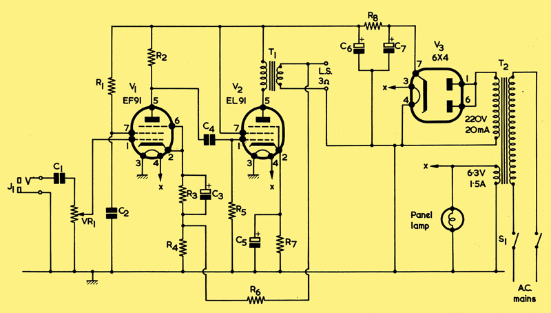
Circuit Diagram with half wave rectification
The signal to be amplified is fed into the miniature jack socket, J1, and through the isolating capacitor C1 to the volume control, and is then applied to the grid of the first valve. This is a high gain pentode, type EF91. Though the EF91 is really an RF amplifier, it is a versatile performer and will be found to work very well at audio frequencies in the circuit shown. The usual anode, screen and cathode bias resistors and capacitors are provided and, additionally, there is in the cathode circuit a small resistor, R4, of which more later.
The amplified signal is passed by way of capacitor C4 to the grid of the output valve an EL91, V2. This is a small power pentode having an output of 1.4 Watts, which is fed to the 3Ω loudspeaker by way of output transformer T1. As the anode current is only 16[m]mA, quite a small transformer can be used and, for the best results, it ought to have a ratio of 70 or 80 to 1. Negative voltage feedback is usually associated with Hi-Fi circuits, but it is worth including in any amplifier because it improves the frequency response and reduces residual hum and the less desirable distortion introduced by the pentode output valve. A feedback voltage is accordingly taken from the output transformer secondary through resistor R6 to the junction of R3 and R4. The relative values of resistors R4 and R6 determine the proportion of the output voltage to be fed back.
Power Supply
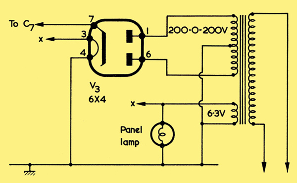
Alternative power supply with full wave rectification
The power requirement is very modest and a small mains transformer able to provide 220 V 20 mA and 6.3 V 1.5 A is quite adequate. Half-wave rectification is given by a 6X4, but a metal rectifier or silicon diode will do just as well provided it has a peak inverse voltage (PIV) rating of not less than 800 V. The end of the diode or rectifier marked red, or with a + sign, is the equivalent of the valve cathode. If the transformer has a full wave HT secondary winding, it is better to use full wave rectification by valve and the circuit above shows how this should be arranged.
At 200 Volts RMS, the 6X4 should have a limiting resistance of 240Ω in series with each anode. With a small mains transformer, this will normally be given by the resistance of the windings themselves. For full wave the resistance of either half of the HT secondary, plus the resistance of the primary, should be 240Ω or more. If less, insert physical resistors, to make the total resistance up to this value, in series with each anode. For half wave the resistance of the HT secondary plus the resistance of the primary should, preferably, be 280Ω or more. If less, insert a physical resistor, to make the total resistance up to this value, between the HT secondary and the anodes.
A 200-0-200 Volt secondary will be adequate here. If the mains transformer primary has taps for different mains voltages, connect to the tap corresponding to the mains voltage to be used. With transformers having lead-out wires, primary taps which are not used should be carefully taped up to prevent short-circuits to adjacent conductors or the chassis. Do not ever be tempted to dispense with the double-wound mains transformer in favour of a circuit in which the mains connects direct to chassis because, apart from the shock hazards associated with such a circuit, this will make the AF input connections live.
The mains input is switched on and off by the rotary double pole switch, S1. Resistor R8 and capacitors C6 and C7 provide smoothing for the rectified HT.
Construction
If small components are employed for the mains and speaker transformer, all the parts may be assembled on a chassis measuring 10 x 3 x 2 inches, as shown in below.
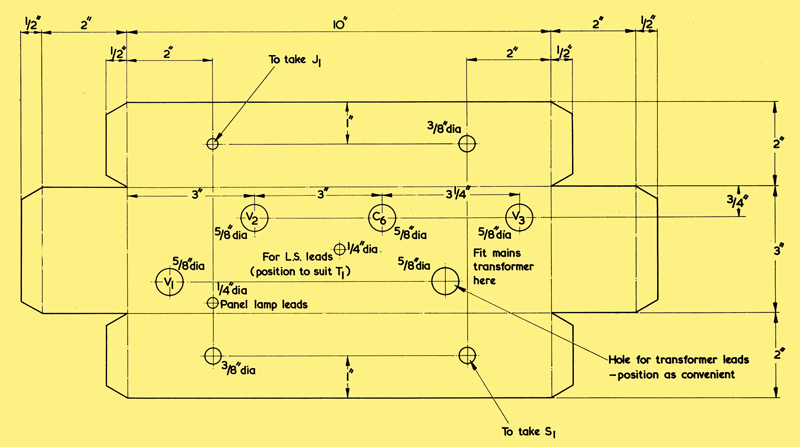
Plan view of the chassis before bending. The end 0.5 inch flanges, at right and left are bent outwards. The hole for C6 may require a different diameter with some capacitors. The material is 18 SWG aluminium
The constructor should first check that these dimensions are suitable for the particular transformers obtained before cutting out the chassis. If the transformers are large and bulky, the chassis dimensions may be modified accordingly. The position of the speaker transformer may be ascertained from the diagram below.
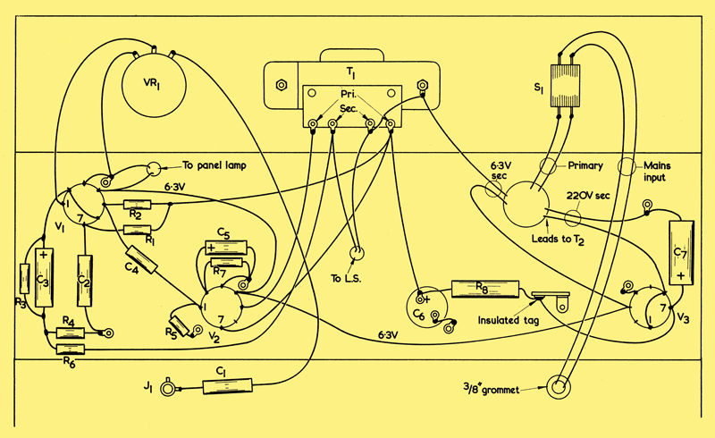
Details of the wiring. The tag layout shown for speaker transformer T1 applies to the component employed in the prototype; other transformers may have a different tag layout and the connections shown here should be modified accordingly.
If a speaker transformer with flying leads instead of a tag-board is used a small tag-strip may be mounted close to the transformer to provide anchors for the primary and secondary connections. The chassis used for the original was slightly shallower than the 2 in shown, and the speaker transformer had a rather large tag-board. These two points made it necessary to cut a rectangular aperture in the deck of the chassis to enable the transformer to be fitted. This problem should not be so troublesome with a chassis depth of 2 in.
The chassis may be made of 18 SWG aluminium. The original fitted compactly into a small wooden cabinet, together with a 7 x 4 in elliptical speaker.
Tinned copper wire of 22 SWG, covered with systoflex, is suitable for all the wiring, which can be tackled in any desired order. The connections to be made are all shown in the wiring diagram. Some of the wires may appear rather long in this diagram, but in construction they should be kept to the minimum necessary length. For instance, C1 will pass directly across the chassis instead of in the manner shown, for clarity, in the diagram. It should be noted that the connections to the primary of T1 may have to be reversed if it is found, on completion, that feedback is positive instead of negative.
In the original, C7 was wire-ended whilst C6 was contained in a can. C6 could, alternatively, also be a wire-ended component. Another alternative could consist of having both C6 and C7 contained in a single can and mounted in the C6 position. If this is done, the high ripple section, usually marked red, is the one to use for C7.
Testing
When construction is complete, it is advisable to check with a meter to see that there are no short-circuits in the HT wiring. Switch the meter to a high ohms range and connect it across C7. There should be a large initial deflection, decreasing slowly to a reading of the order of 1 MΩ or more as C6 and C7 become charged from the meter battery. If the meter leads are applied with incorrect polarity, the final high resistance reading may not be obtained due to the presence of the electrolytic capacitors, whereupon the leads should be reversed. With conventional test-meters switched to an ohms range, correct polarity for the insulation test will be given with the positive meter lead to chassis.
If all is well, power may be applied. The speaker should, of course, be connected.
As the amplifier warms up, it will scream disrespectfully at the constructor if the feedback happens to be positive. Do not reproach yourself - even the experts cannot predict the right connection. Switch off nonchalantly and with a flourish of the soldering iron, reverse the connections to the primary of the output transformer to make the feedback negative.
Operation
It remains to make up a screened lead about 2 ft long with a miniature jack plug at each end. Insert one plug into the amplifier and the other into the socket provided for the earpiece in a receiver and all is set. If the current consumption of the receiver varies with the setting of the volume control, battery life can be prolonged by using a low setting and bringing the signal up to the desired level in the amplifier.
Cabinet
Upon promotion to domestic service, the prototype, which had hitherto rested naked upon the bench, was given the plywood cabinet shown in the illustration. Details of the measurements and method of construction are given below.
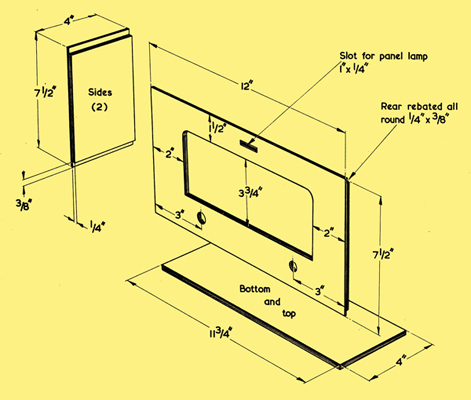
Making a cabinet. The material is faced plywood. The spindle holes may be marked out from the chassis.
Faced plywood 0.375 in thick is very suitable material. The joints can be secured very satisfactorily with panel pins and glue and quite a good exterior finish can be produced by staining and varnishing. The original was French polished, but this was not observed to improve the performance!
A rectangular slot was provided in the front panel for the pilot lamp. The speaker aperture should be covered with Tygan or some similar material, secured with impact adhesive. The 7 x 4 in loudspeaker should first be fitted to a piece of 0.125 in (3 mm) hardboard in which a suitable aperture has been cut and the whole fitted into the cabinet with wood screws.
To make the securing holes for the chassis, first clamp it in position. Then drill upwards, through the bottom of the cabinet and through the end flanges of the chassis, two holes, one at each end. If the holes in the wood are then enlarged and wood screws of suitable size inserted, they will have a self-tapping action as they enter the aluminium and will keep the chassis very firmly in position. The panel lamp slot can be covered with a piece of coloured Perspex or even paper, and the lamp holder secured in position with a small wood screw.
A carrying handle at the top of the cabinet is a useful addition and four small pieces of rubber to act as feet, secured to the bottom with Evostick, will avoid scratches on any polished surface on which the unit may stand.
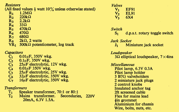
Components list
|