|
Beam Tetrodes and Pentodes
Previously we looked at the various classes of operation in which a valve may be employed. These were Class A, B and C, together with the intermediate Class AB. In all cases a subscript figure may be added after the letter indicating the class, this figure being 1 when no grid current flows during the input cycle, and 2 if grid current flows during the more positive parts of the input cycle.
We now turn our attention to the various valves which may be employed in an AF output stage.
Output Valves
In the circuits illustrating output stage operation used in these articles up to now, we have shown triode valves in order to render explanation more simple. AF output stages may alternatively, however, employ pentode valves or beam tetrode valves instead of triodes. Both the latter types provide a higher output for the same HT power consumption than does a triode output valve of comparable type. Also, they are both more sensitive than the triode and require a lower input signal for the same output power. As a result of these two advantages, pentodes and beam tetrodes are almost invariably employed instead of triodes in practical valve AF output stages.
We have previously discussed the use of pentode and tetrode valves as voltage amplifiers, but we have not yet dealt with pentode output valves, nor with beam-tetrode valves. This we shall next proceed to do.
Readers of the earlier issues will recall that the IaVa characteristic curves of a tetrode voltage amplifier valve have the appearance illustrated in (a) below.
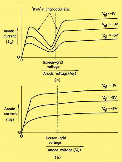
(a) These IaVa characteristic curves for a voltage amplifier tetrode demonstrate the distinctive 'kink' given by this type of valve
(b) The 'kink' is eradicated in the pentode, due to the presence of the suppressor grid.
As may be seen, there is a 'kink' in the curves over the range of anode voltages from slightly above zero to somewhat in excess of screen-grid voltage, after which the curves become linear. As was explained in the previous articles the 'kink' is the result of secondary electrons from the anode (released by electrons arriving from the cathode) being attracted towards the screen-grid. Indeed, over the section of the characteristic curves where anode current decreases as anode voltage increases, secondary electrons are leaving the anode at a greater rate than the rate of electrons arriving from the cathode, and the curves exhibit negative resistance.
As was also discussed previously, the pentode valve has a suppressor grid at cathode potential interposed between the screen-grid and the anode, its function being to repel the secondary electrons emitted from that anode. In consequence, the 'kink' in the IaVa characteristic of the tetrode disappears and the IaVa curves for the pentode have the general appearance shown in (b) above. At the right, these curves are similar to the linear sections of the IaVa curves for the tetrode, but the linearity now carries on over to the left, continuing to well below screen-grid voltage.
An AF output pentode is fundamentally the same as a pentode employed for voltage amplification, apart from the fact that it is designed to operate at higher currents and is therefore capable of feeding a higher power to a load in its anode circuit. The IaVa curves of an output pentode have the same appearance as those in (b) above, which are for a pentode voltage amplifier, except that the output pentode curves would represent a wider range of grid voltages, typically from Vg=0 to Vg=-15. Also, the currents along the Ia axis would typically be in tens or hundreds of milliamps instead of in single milliamps, as would occur with the voltage amplifier pentode.
The Beam Tetrode
An AF output tetrode whose IaVa characteristic exhibited the 'kink' illustrated in (a) would be of little use in practice because of the considerable distortion which would be caused if, during the output cycle, the anode voltage approached the screen-grid voltage. With an output pentode, on the other hand, this type of distortion is absent, even when the anode voltage is considerably below the screen-grid voltage. In consequence, the pentode lends itself very well to use as an AF output valve.
The beam tetrode is an output valve which overcomes the effects of secondary emission from the anode in a different manner to that given in the pentode. In the beam tetrode the wires which form the control grid and screen-grid are in optical alignment. The spacing between wires in both grids is the same and, assuming that the cathode is vertical, are at the same horizontal level.
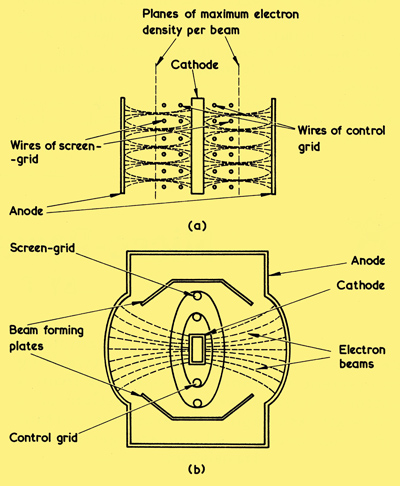
(a) Cross-sectional side view of a beam tetrode, illustrating how the electron beams tend to converge at two planes of maximum electron density per beam. A practical beam tetrode would have longer electrodes than are illustrated here
(b) Top view, showing how the beam forming plates, which do not appear in (a), restrict the horizontal beams to areas in which the optical alignment between control grid and screen-grid wires has greatest effect.
Also, there is a greater spacing between the screen-grid and the anode than is normal with a pentode.
Looking out from the beam tetrode cathode, the wires of the screen-grid are 'shadowed' by the wires of the control grid. Electrons leaving the cathode are forced into horizontal beams by the wires of the control grid, the vertical height of these beams (as shown in (a)) decreasing as the electrons continue towards the anode. If the beam- forming process were perfect, the beams of electrons would pass right through the wires of the screen-grid without striking them, although they would still be subject to the electric field the screen-grid provides. In practice, some of the electrons strike the screen-grid, but the quantity is much lower than with the normal pentode construction. In point of fact, screen-grid current in the beam tetrode is about a third of the screen-grid current in a comparable pentode. After leaving the screen-grid the beams of electrons still continue to converge until, at a vertical plane some distance outside the screen-grid, they achieve maximum electron density per beam. After this the electrons in each. beam then fan out vertically and, later, strike the anode. The plane at which maximum electron density occurs can be looked upon as a virtual cathode, and it offers repulsion to secondary electrons released from the anode. So far as the anode is concerned, the virtual cathode is similar to that of a diode, and the same freedom from secondary emission effects is given. Indeed, a feature of the beam tetrode valve is a very rapid rise in anode current as anode voltage is initially increased from zero, this being reminiscent of the performance of a diode with close cathode-anode spacing.
Two beam forming plates (also known as beam confining plates or, simply, beam plates) are fitted around the vertical edges of the screen-grid as shown in (b). These are connected to cathode and cause the horizontal beams of electrons to be confined to the regions where the optical alignment between control grid and screen-grid wires is at its best. Thus, only beams of electrons which are capable of providing the virtual cathode plane are allowed to pass to the anode. (We have referred to a single virtual cathode plane but, as may be seen from inspection of the diagram, there are really two similar planes, one on either side of the cathode.)
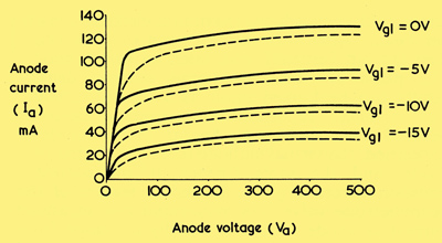
The solid lines show typical IaVa characteristic curve shape for a beam tetrode. The dashed lines represent the IaVa characteristic curves of a comparable output pentode.
A typical family of IaVa characteristics for a beam tetrode are given above, these being compared with typical output pentode curves, which are shown in dashed line. It will be noted that the linear sections of the beam tetrode curves extend a little farther to the left than occurs with the pentode curves, whose transition from the nearly horizontal condition to the nearly vertical condition is less abrupt. This factor indicates that somewhat more power may be obtained, at an acceptable distortion level, from a beam tetrode than from a comparable pentode.
The circuit symbol for a beam tetrode is shown below. It will be seen that this is similar to that for the pentode except that two symbols to represent the beam forming plates now appear between the screen-grid and the anode in place of the suppressor grid of the pentode. In the diagram the beam forming plates are connected to a separate valve pin, which may be externally connected to cathode (or to chassis). In some beam tetrodes the beam forming plates are connected to the cathode internally. In the past, beam tetrodes have been described by the term kinkless tetrode, the adjective deriving from the absence of a 'kink in the IaVa characteristic.
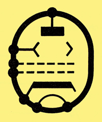
The circuit symbol for a beam tetrode. The two electrodes between the screen-grid (g2) and the anode are the beam forming plates. It is common practice to show a connection to one beam forming plate only (as illustrated here) the connection to the other plate being assumed.
Next we shall briefly examine output pentode and beam tetrode performance, after which we will carry on to the ultra-linear output circuit and the subject of phase-splitters.
|