|
Converting a rear-projection television chassis
For various reasons projection television for the home has not been a success, either here or in the United States. When manufacturers were faced with the demand for bigger pictures a few tentatively tried some rear-projection models, but gradually the trend has swung over to larger and larger cathode-ray tubes for direct viewing. Today there are only a few projection models available for home use, and I believe all of these are rear-projection types.
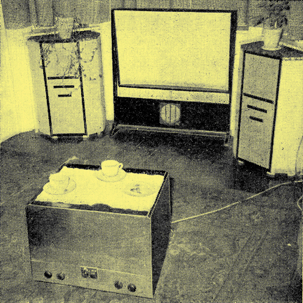
Arrangement of the modified projection set and screen in the author's living-room.
The objections which have been raised against this type of receiver may be summarized as follows:-
- An insufficiently brilliant picture, necessitating viewing in a nearly dark room.
- In the case of forward projection, a large and unwieldy console standing in the centre of the room, with mains and aerial leads lying across the floor.
- Rather poor EHT regulation, with consequent focus instability with changing picture content.
- Complicated circuitry and less reliability.
It is the purpose of this article to show that all these objections can be overcome, partly or wholly, in the case of forward projection in a normal-sized living room.
Dealing with the objections in order, first of all it must be remembered that nearly all commercial forward-projection receivers are designed specifically for use in schools, hospitals, etc., where an audience of perhaps thirty or forty people has to be catered for. This necessitates a large, sometimes flat screen, usually 4 ft x 3 ft, situated fairly high on the wall - a position which will give maximum reflection of any ambient lighting in the room.
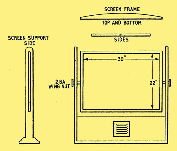
Constructional details of the screen with the loudspeaker built in below.
At home a different procedure may be adopted. In the writers case the screen is mounted in a wooden framework which gives adjustable height and tilt. The centre of the screen is only 26 in from the floor and it is tilted at about 10° from the vertical. The screen size of 30 in x 22 in is considerably larger than the largest direct-view picture obtainable, and is just about optimum for the room size of 14 ft x 12 ft.
The room lighting for normal viewing at present consists of three 100 Watt lamps reflecting from the ceiling. This gives adequate illumination, at the same time permitting a reasonably good picture to be enjoyed. On special occasions - for example, when the family wishes to sit down and enjoy a good play - a small standard lamp is used, when the performance can only be compared with a good cinema picture. By making the screen slightly concave in a horizontal direction a wide angle of viewing is obtained, and its forward tilt and low position give minimum reflection of ambient lighting. Activated aluminium screens of similar design may be obtained from PAM, Ltd., of Guildford, Surrey.
Compact Console
Coming now to objection (2), it is quite possible to make a forward projection console reasonably small. The particular one in use by the writer at the moment is built around a Philips 704A chassis and measures only 15 in high by 21 in wide by 18 in front to back. By fitting the optical box at the rear of the chassis, ie, farthest from the screen, the console itself is brought nearer to the screen and farther from the centre of the room. The main reason for making the console as low as possible is to enable the picture to be viewed from normal armchair height over the top of it, i.e., directly in front of the screen where the picture is at its brightest. In its position about 5 ft from the screen (64 in from the corrector plate to screen) the console also comes in useful as a coffee table.
The best way to overcome the difficulty of untidy leads is to run aerial, mains and speaker leads in one piece of sleeving from the console to two sockets on the skirting board near the screen - one for mains and one from the aerial and speaker. It will be found far better to place the loudspeaker with the screen rather than in the console, partly to avoid the 'disembodied voice' effect and partly to save precious space in the console. Two leads have to be run to the console anyway, so that the extra leads for the speaker are no problem.
With regard to objection (3), this problem solves itself to a certain extent with forward projection. Owing to the greater light transfer efficiency as compared with rear projection, the beam current of the CRT need not be so high for a bright picture and consequently the EHT generator need not be driven so hard. The regulation of any of the commercial rear-projection models will usually be quite adequate, but should greater focus stability be desired there are various ways of doing this which should be well within the ingenuity of Wireless World readers. One solution is to introduce a certain amount of vision AGC which is based on the peak white in the picture. This degrades the contrast values to a certain extent but gives a good stable picture.
The fourth objection, of complicated circuitry and un-reliability, is simply not true. The only additions in a projection receiver are the EHT generator and a safety circuit which blacks out the beam to prevent burning of the screen if either timebase should fail. In the writers experience these sets give very little trouble and when they do the servicing is usually straightforward.
At the present time there are many old rear-projection sets on the second-hand market and the only major modification necessary for conversion to forward projection is the changing of the corrector plate on the Mullard optical box to give a throw of 64 inches. I understand that this service can now be done through any Philips dealer by M Bender (Northern), Ltd., of Newcastle-upon-Tyne.
It is hardly possible to give detailed instructions for the mounting of the optical box as this will depend entirely on the particular chassis chosen for conversion. From the point of view of ease of servicing and initial setting-up, etc., it will be found better to mount the box directly on the chassis rather than fix it to the interior of the cabinet. It must be rigid and have some means of varying the angle of throw in a vertical direction through about 5-10 degrees.
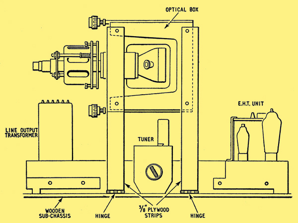
Method of mounting the optical box on the chassis of the receiver.
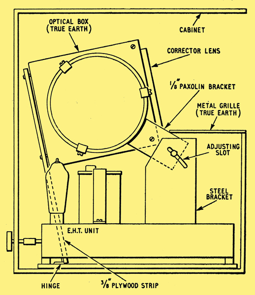
The Philips series 600A, 1800A and 704A receivers, being very compact, are particularly suitable for conversion, and in these the optical box may mounted approximately in its original position, i.e., next to the EHT unit. Two pieces of 3/8 in plywood l.25 in wide by 12 in long are bolted to the back of the box and have their lower ends joined to the wooden sub-chassis by hinges. The front of the box is bolted to two steel brackets fitted to the main chassis at right angles to the box. The bolts connecting the box to these brackets run into slots in the brackets to allow the vertical angle to be varied. Incidentally, with this method of mounting it will be found that a turret tuner will just ?t under the box, with its station selector knob nicely in line with the other controls. It must also be remembered that these chassis are live, and suitable precautions should be taken to ensure that no part of the chassis is accessible from outside the cabinet.
Method of mounting the optical box on the chassis of the receiver.
It does not come within the scope of this article to deal with circuitry but merely to give suggestions for the general arrangement of the console and screen for home use. If these suggestions are carried out I can promise that the result will be a pleasant surprise, especially to those who have only seen forward projection at exhibitions or in shops. In spite of the fact that, in theory, it is impossible to obtain a real black on a silver screen in a lighted room [1] Projection Television, Letters to the Editor, December, 1957, issue., it will be found in practice that the contrast range is at least as good as a direct-view receiver. This is probably because black is only comparative in any television receiver and the extremely good highlights obtained on the silver screen make the blacks appear just that much blacker.
Better Picture Quality
One of the main criticisms of back projection has been the 'softness' associated with this type of picture. This effect is mainly due to the light scattering which cannot be avoided with even the thinnest of translucent screens but which does not occur with forward projection, where the light is beamed directly on to an opaque screen. The absence of external mirrors, which slowly lose their efficiency through the accumulation of dust, etc., is another great advantage over rear projection. It would probably be fair to say that the general tone or 'goodness' of the forward projection picture lies somewhere between that of a good rear-projection set and that of a direct-view type, with a bias toward the last-mentioned. When one considers the many other advantages of forward projection, eg, the really big picture and the beautifully even focus, the change is certainly worth considering.
In conclusion, not the least of the advantages of forward projection is the low cost of replacing the CRT, which is only about one-third of the price of even a 21 in direct-view tube, and unless I have been exceptionally lucky the useful life of these projection tubes is, if anything, longer than that of their big brothers.
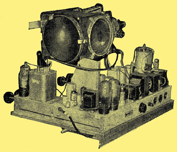
The modified receiver with the optical box mounted on the chassis.
Reference
- Projection Television, Letters to the Editor, December, 1957, issue.
See also MW6/2, CV1737 & The Optics of Projection Television.
|