|
A general review
Those of us who are in search of perfection in audio amplifiers must often have looked askance at the output transformer. In general it would be possible to reduce the non-linearities in an amplifier below any desired value by the application of a sufficient amount of feedback. However, as is well known, the output transformer produces undesirable phase shifts at the extreme ends of the audio spectrum which limit the amount of feedback which can be applied before instability sets in. These phase shifts also decrease the effective feedback at these extreme frequencies and this causes increased distortion in these regions. Varying core losses, hysteresis effects, matching variations, and incomplete coupling between the primaries also more directly increase the distortion, and this increase also is more pronounced at the frequency extremes.
Modern transformer design techniques of sectionalized windings, and particularly the use of C-cores, have to a large extent overcome these disadvantages in practice; but this has naturally given rise to an increase in price, and the fundamental limitations still remain.
Increased Possibility of Class B Operation
Using loudspeakers of normal efficiency and impedance (15 Ohm) in an average living room an accepted peak power requirement from the amplifier is of the order of fifteen watts. In this case if there is no output transformer we will obviously require currents of the order of one ampere from the output valves.
The problem of obtaining these currents is somewhat eased because in transformerless amplifiers Class B operation of the output valves becomes more feasible than such operation is in an amplifier with an output transformer. Normally in Class B operation using an output transformer incomplete coupling between the two half primaries produces transients when the valves cut off. These transients produce distressing audible distortion and are very difficult to eradicate, though a special bifilar transformer with both cathode and anode feeds designed by McIntosh and Gow [1] F H McIntosh and G I Gow, 'Description and Analysis of a New 50 Watt Amplifier Circuit', Audio Eng., Vol. 33, December 1949, p. 9. does succeed in doing so.
In Class B operation owing simply to the higher outputs the general distortion is higher but this is not seriously so and can, of course, be reduced by increased feedback.
High-Impedance Loudspeakers?
Allied to the difficulty of obtaining sufficient current from the output valves is that of matching, without too much distortion, the comparatively high valve impedance (of the order of a few thousand ohms) to the low impedance of the loudspeaker voice coil.
An obvious solution to both these problems is to use loudspeakers of higher impedance, but here the necessity of using thinner wire to keep the voice coil weight down produces its own problems. A few speakers of impedances in the range of 200-500 Ohms have, however, been marketed, but there is not the usual variety of models available. Readers will realize the possibility that the newer electrostatic speakers will fit more smoothly into such a system, though their capacitive nature increases the matching problem.
In general by suitably paralleling output valves a transformerless amplifier for high-impedance loudspeakers can be adapted for low-impedance ones, so that the general features of the various designs can be considered without regard to the voice-coil impedance.
Straightforward Methods
A first approach is simply to use normal circuits with the loudspeaker directly replacing the output transformer or load [2] V Brociner and G Shirley, 'The Output-Transformer-less Amplifier', Audio Eng., Vol. 36, June 1952, p. 21., bearing in mind that it will often be more convenient to connect the speaker in the cathode or low-voltage side of the valve.
Such designs generally involve capacitive coupling to the loudspeaker or direct current through the voice coil. Capacitive coupling requires almost impossibly high values of capacitor for good low-frequency response and small phase shift in the case of low impedance loudspeakers, and may produce distortion due to hysteresis in the capacitor.
Direct current in the voice coil would move it toward the positions of non-linearity for the suspension and non-uniformity of the magnetic field and in practice give a considerable increase in distortion. The possibility of increasing the linearity of the suspension (and thus decreasing the distortion), while maintaining sufficient restoring force to allow the required audio power to be developed, has already been largely exhausted in the design of conventional loudspeakers.
Distortion caused by a non-uniform magnetic field could be avoided by making the voice-coil longer than the field so that the same length is always immersed in the field. This arrangement is often used in bass loudspeakers where the increased weight of the voice-coil is less important. An equivalent method would be to lengthen the magnetic field but the larger magnets required would increase the cost. The alternative of having the voice-coil initially asymmetrical with respect to the magnetic field would require a change in the initial displacement for different amplifiers and is thus rather impracticable [3] For another method see H A Watt, 'The Post-ultimate Amplifier', High Fidelity, Vol. 6, April 1956, p. 62..
This simple approach also unfortunately needs a centre-tapped voice coil for normal push-pull operation. For ultra-linear operation two more tappings are even necessary! From the point of view of requiring as little and as practical a change as possible in existing loudspeaker design this approach is seen to be inadequate.
Some sort of balanced arrangement whereby direct current in the voice coil is avoided would be an improvement. A straightforward circuit along this line is described by Fletcher and Cooke [4] E W Fletcher and S F Cooke, 'Cathode-follower Loudspeaker Coupling', Electronics, Vol. 24, November 1951, p. 118.. The authors use a simple push-pull cathode follower arrangement shown schematically in Fig. 1.
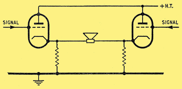
Fig. 1. Fletcher-Cooke output stage.
In order to obtain 12 Watts of peak power in a 16-Ohm loudspeaker 16 6AS7Gs were necessary. No distortion figures were quoted, and the damping was not very good (the output impedance was 23 Ohms) but the authors did not use any overall negative feedback. In such cathode follower circuits low-impedance loudspeakers have an advantage in that the voltage requirements from the driver are not so serious as is usually the case.
Series Connected Output Stages
Most other circuits use a series connected output stage, with either a single or push-pull input to this stage. In either case since the valve outputs in the load add together the optimum value for this load is less than half of that in the conventional push-pull arrangement. This type of circuit thus considerably eases the matching problem. It is also often easier to arrange DC connections between earlier stages and the output valves which improves the low frequency response and decreases the phase shift in this region.
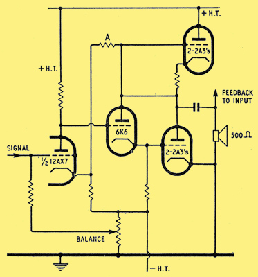
Fig. 2. The Stephens amplifier with 12AX7, 6K6 & 2A3 valves.
Using a single input, series connected, output stage two commercial amplifiers have been developed, by Stephens [5] F H Gilbert, 'Commercial O-T-L Amplifier of Unique Design', Audio Eng., Vol. 36, August 1952, p. 46; and F H Gilbert, 'An AF Amplifier Without Output Transformer', Radio and Television News, March 1953, p. 45. and Philips [6] Wireless World, Vol. 62, October 1956, p. 475, and Wireless and Electrical Trader, Vol. 103, September 1st 1956, p. 618., both for capacity connected high-impedance loudspeakers. Schematic diagrams for these are shown in Figs. 2 and 3.
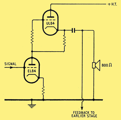
Fig. 3. Philips output stage with UL84 & EL84 valves.
In both cases the signal from the lower output valve is fed to the grid of the upper so that the input signal varies the voltage across the output valves in opposite directions. More complicated power supply arrangements could have avoided the necessity of capacity connections to the loudspeakers. The circuit of the Stephens amplifier shows how DC connections between early stages may be arranged in this type of circuit. The resistor A provides negative feedback and serves to stabilize the bias on the 2A3s. With about 40 dB of feedback 3rd harmonic distortion is of the order of 0.4 per cent for 20 Watts RMS output into the 500 Ohm load. Unfortunately, in both these amplifiers the voice coil does not provide a sole common load for the two output valves because they also partially load each other. Although cancelling of even harmonic distortion products could still be obtained by arranging for the output valves to give equal amounts of such distortion in the voice coil, this balancing would be difficult if not impossible, with the few variables available.
Push-Pull Series Connected Output Stages
The last-mentioned disadvantage does not apply if the output valves are series connected with push-pull input. In this case the optimum output impedance is one quarter of that for normal push-pull operation. If, however, the phase splitter and output valves are not correctly designed together it is difficult to retain equal drive in the output valves as the loudspeaker impedance changes.
An example of this difficulty arises in an amplifier described by Dickie and Macovski [7] D P Dickie, Jr., and A Macovski, 'A Transformerless 25 Watt Amplifier for Conventional Loudspeakers', Audio Eng., Vol. 38, June 1954, p. 22.. Omitting a push-pull driver stage the phase splitter and output stages are schematically as in Fig. 4.
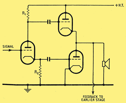
Fig. 4. Dickie-Macovski output stage.
Here it will be seen that the voice-coil load is coupled so that it provides feedback to the grid of the upper valve. Thus the input to this valve has to be increased and the resistor R1 is made greater than R2. However the variation of voice-coil impedance over the frequency range (which may easily be of the order of 5 to 1) prevents exact adjustment by this means except over a narrow frequency band. In this amplifier the effect of this impedance variation is reduced by suitably shunting the voice coil; an example of such a shunt being simply a 0.01μF capacitor and a 16 Ohm resistor in series. This prevents the rise in impedance at high frequencies produced by the inductive voice coil and thus avoids instability caused by increased feedback and phase shift. The anode loads of the push-pull driver stage could also be adjusted to give better balance.
In this amplifier there is one voltage amplifying stage before the phase splitter and 3 6082 valves (26.5 Volt versions of the 6AS7G) operating nearly in Class B in the output stage. With 40 dB of overall feedback the harmonic distortion was 0.4 per cent for 25 Watts RMS. into a 16 Ohm load.
Essentially the same balancing difficulty arises in a variation of the circuit of Fig. 4 described by Onder [8] K Onder, 'A New Transformerless Amplifier Circuit', Journal of the Audio Eng. Soc., Vol. 1, October 1953, p. 282; and K Onder, 'Audio Amplifier Matches Voice-Coil Impedance', Electronics, Vol. 27, February 1954, p. 176.. Here instead of simply paralleling output valves to give increased power they are arranged in a bridge circuit (shown schematically in Fig. 5) which increases the optimum load to four times that for a parallel arrangement.
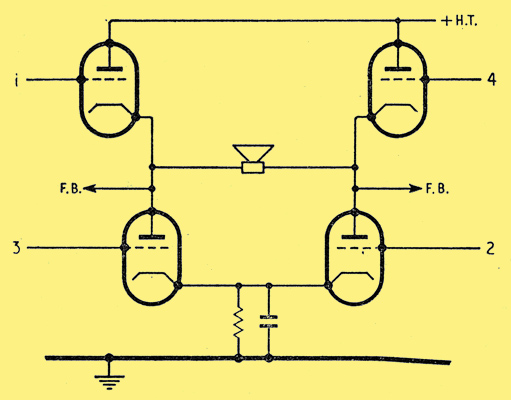
Fig. 5. Onder output stage.
Diagonal valves are run in phase, suitable driving voltages being obtained from a push-pull stage as in Fig. 6, this arrangement giving the necessary greater input to the upper tubes. An ordinary concertina phase splitter with suitable tappings on the loads could, of course, also be used.
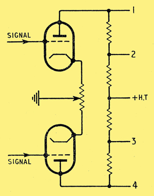
Fig. 6. Onder driver stage.
Here again using a balancing potentiometer as in Fig. 6, DC connections become possible.
In this amplifier there is a see-saw type of phase inverter before the driver, and 2 6AS7G valves operating in Class A in the output stage. With about 15 dB overall feedback the inter-modulation distortion was 0.7 per cent for 9 Watts into a 400 Ohm load.
Equalization of Drive in the Output Valves
If we return now to Fig. 4 equal drive in the output valves can be obtained very simply as described by Futtermanf [9] J Futterman, 'An Output-Transformerless Power Amplifier', Journal of the Audio Eng. Soc., Vol. 2, October 1954, p. 252. by returning the earthy end of R2 to the junction of the output valves as in Fig. 7.
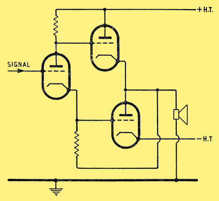
Fig. 7. Futterman output stage.
In this case both output valves are acting as cathode followers so that the voltage requirements from the phase splitter are large. However, the load is in the input to this valve in the correct sense to provide positive feedback so that a much lower voltage is actually required.
In the amplifier described in this reference ( [9] J Futterman, 'An Output-Transformerless Power Amplifier', Journal of the Audio Eng. Soc., Vol. 2, October 1954, p. 252.) there is a pentode, high gain, voltage amplification stage before the phase splitter. The cathode return from this pentode is taken to the tap of a potentiometer across the load so that varying amounts of negative feedback may be applied. There was in fact some difficulty in obtaining sufficient gain to give enough feedback to reduce the distortion sufficiently, but a phase splitter giving gain could be used. Using 14 type 12B4 valves operating in Class B in the output stage, with 48 dB of overall feedback the harmonic distortion was 0.1 per cent for 20 Watts into a 16 Ohm load. Square wave tests on this and the amplifier of [7] D P Dickie, Jr., and A Macovski, 'A Transformerless 25 Watt Amplifier for Conventional Loudspeakers', Audio Eng., Vol. 38, June 1954, p. 22. already described give very impressive results even at 20 kHz, with very short rise times and no overshoot.
A more complicated way of obtaining this equal balance, by applying extra feedback to the lower output valve in Fig. 4 is described by Coulter [10] W H Coulter, 'Amplifier Circuit having Series-connected Tubes', US Pat. No. 2,659,775, Brit. Pat. No. 688,273. This patent is described in Audio Eng., Vol. 38, March 1954, p. 2. and illustrated in Fig. 8.
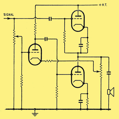
Fig. 8. Coulter output stage.
Here the upper output valve is fed directly from the input. A suitable fraction of this input has its phase inverted by another valve and is then applied to the grid of the lower output valve. By taking the cathode feed for the phase inverter from the tap of a potentiometer across the load, negative feedback is applied to this inverter and thus to the lower output valve. The amount of this negative feedback is adjusted to compensate for that produced by the load in the upper valve.
A disadvantage of this arrangement is that the distortion in the input to the lower valve is greater than that to the upper as this input has to pass through an extra voltage amplifying stage (the phase inverter); and the even harmonics of this extra distortion cannot be cancelled in the output stage. Furthermore, the degeneration caused by the speaker varies with its impedance, whereas the feedback is a constant fraction of the output voltage.
This general type of output stage has been recently applied to a transistor circuit by Cossors [11] Electrical and Radio Trading, Vol. 32, October 6th 1956, p. 54.. Transistors have an encouraging future in transformerless amplifiers as their voltage requirements are much lower, and a considerably higher overall efficiency should be possible. In the Cossor circuit equal drive in the output transistors is obtained by an input transformer. This transformer also avoids DC unbalance in these transistors but is contrary to the general philosophy of such amplifiers.
Returning again to Fig. 4, perhaps the best way of obtaining balanced inputs to the output valves is, as described by Peterson and Sinclair [12] A Peterson and D B Sinclair, 'A single-ended Push-Pull Audio Amplifier', Proc.IRE, Vol. 40, January 1952, p. 7., to take the anode supply for the phase-splitter from the junction of the output valves as in Fig. 9.
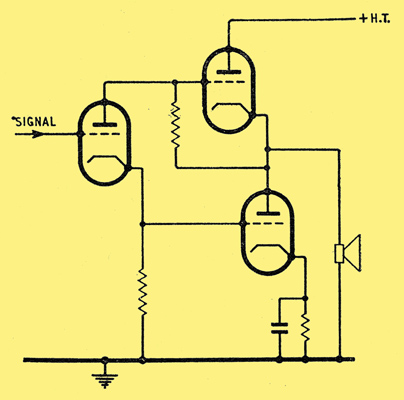
Fig. 9. Peterson-Sinclair output stage.
In this case the input voltages to the output valves are always developed between cathode and grid, so that the load does not produce a cathode follower effect in either valve and there is no unbalance. A disadvantage is the negative feedback produced by the load on the supply voltage for the phase-splitter. This circuit also is susceptible to DC connection.
The authors give a general discussion of this type of amplifier using transformers solely as matching devices. No practical details of a strict transformerless amplifier are given.
Extended Class A?
Another novel type of circuit that may perhaps be of value in these amplifiers was given the name, extended Class-A, by the author [13] H T Sterling, 'Extended Class-A Audio', Electronics, Vol. 24, May 1951, p. 101.. Here a triode and tetrode are run in parallel with their grids and anodes directly connected. The valves are biased for normal Class A, operation for the triode and this usually cuts off the tetrode, so that the arrangement acts as a triode for small signals. When the signal becomes sufficiently large (usually about one third of the maximum) the tetrode starts drawing current and increasingly controls the operation. This gives the transfer characteristic a slight curve but this is not serious. The circuit should combine the advantages of the low output impedance of triodes with the high current carrying characteristic of tetrodes. The idling anode current also is only about one third of the usual amount, or, in other words, for a given valve the maximum power obtainable is greatly increased.
Power Supplies
It will be noted that the schematic diagrams in many cases envisage more than the usual number of power supplies, especially when those for screens and grids are worked out, and particularly if DC connections are desired. This complication is not as great as may be imagined when voltage doubling circuits, the avoidance of mains transformers, and direct series running of the heaters are considered. Moreover, due to the large amounts of negative feedback used, the hum in the output is generally reduced so much that chokes need not be used in the supplies. In fact, such chokes are often undesirable, as the impedance of the HT supply to the output valves must be low compared with the load to avoid loss of power.
Practical Choice of Output Valves
To return to some earlier remarks, one of the biggest practical difficulties is simply that of obtaining output valves that can pass the necessary current. Here from the cost point of view more than one valve will almost certainly be required for each side of the output stage. Bearing in mind that certain valves can be obtained very cheaply, it may be more economical to use a large number of one valve rather than fewer of another. Valves made primarily for other purposes, such as a television line scan or current stabilization, can also sometimes be of use. The resultant optimum load should, of course, be made as small as possible, though increased distortion due to mismatch may be removable by sufficient feedback.
References
- F H McIntosh and G I Gow, 'Description and Analysis of a New 50 Watt Amplifier Circuit', Audio Eng., Vol. 33, December 1949, p. 9.
- V Brociner and G Shirley, 'The Output-Transformer-less Amplifier', Audio Eng., Vol. 36, June 1952, p. 21.
- For another method see H A Watt, 'The Post-ultimate Amplifier', High Fidelity, Vol. 6, April 1956, p. 62.
- E W Fletcher and S F Cooke, 'Cathode-follower Loudspeaker Coupling', Electronics, Vol. 24, November 1951, p. 118.
- F H Gilbert, 'Commercial O-T-L Amplifier of Unique Design', Audio Eng., Vol. 36, August 1952, p. 46; and F H Gilbert, 'An AF Amplifier Without Output Transformer', Radio and Television News, March 1953, p. 45.
- Wireless World, Vol. 62, October 1956, p. 475, and Wireless and Electrical Trader, Vol. 103, September 1st 1956, p. 618.
- D P Dickie, Jr., and A Macovski, 'A Transformerless 25 Watt Amplifier for Conventional Loudspeakers', Audio Eng., Vol. 38, June 1954, p. 22.
- K Onder, 'A New Transformerless Amplifier Circuit', Journal of the Audio Eng. Soc., Vol. 1, October 1953, p. 282; and K Onder, 'Audio Amplifier Matches Voice-Coil Impedance', Electronics, Vol. 27, February 1954, p. 176.
- J Futterman, 'An Output-Transformerless Power Amplifier', Journal of the Audio Eng. Soc., Vol. 2, October 1954, p. 252.
- W H Coulter, 'Amplifier Circuit having Series-connected Tubes', US Pat. No. 2,659,775, Brit. Pat. No. 688,273. This patent is described in Audio Eng., Vol. 38, March 1954, p. 2.
- Electrical and Radio Trading, Vol. 32, October 6th 1956, p. 54.
- A Peterson and D B Sinclair, 'A single-ended Push-Pull Audio Amplifier', Proc.IRE, Vol. 40, January 1952, p. 7.
- H T Sterling, 'Extended Class-A Audio', Electronics, Vol. 24, May 1951, p. 101.
See Also the follow-up article from 1958.
|