|
The construction of a powerful push-pull high fidelity audio amplifier always entails considerable expense. Whilst this may be well worth while to many people, there are others (especially new-comers to electronics) who require a flexible circuit for a simple cheap amplifier for gramophone and radio reproduction which will give a few Watts output at reasonably good fidelity. A small audio amplifier is also useful as a stand-by and for use when a large amplifier is unnecessary.
The circuit of the amplifier
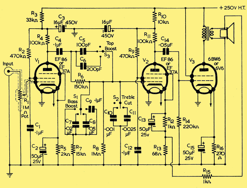
The circuit to be described employs two EF86 valves as voltage amplifiers and a 6BW6 power output valve. These valves are noval based single-ended miniatures, but there are other types with similar characteristics which are quite suitable. The EF86 valves may be replaced by EF37A valves which have. an international octal base and a top cap grid connection. Other octal types suitable for V1 and V2 are 6J7 and EF36 (VR56) which are obtainable cheaply on the surplus market but are more likely to introduce hum than the EF86 or EF37A. The 6SJ7 is a suitable single-ended octal type. The noval based 6BW6 output valve may be replaced by the octal 6V6 or, if the anode voltage does not exceed 250 volts, by the miniature 6AQ5 with a B7G base. If a 6BW6 is used the beam plates should be connected to the cathode; this is done internally in the other two types of output valve.
Negative feedback is used from the output transformer secondary to the cathode circuit of V2. Any distortion in the last two valves or in the output transformer is reduced by the feedback, but it is nevertheless important to use a good transformer. The primary impedance of the transformer should be about 5,000 Ohms and the secondary impedance should be about the same as that of the speaker to be used. The feedback circuit must be connected the correct way round; this is found by trial and error. If the gain is not greatly reduced when the feedback circuit is connected, or if the amplifier oscillates, the feedback wires (one is earthed) from the secondary of the output transformer should be reversed. The negative feedback greatly reduces distortion and extends the frequency range of the amplifier somewhat. It can, however, cause a great deal of distortion and instability if it is not connected correctly or if the output transformer is very poor. The amount of feedback is increased if the value of R15 (1,000 Ω in the amplifier circuit ) is reduced. The value of R15 may be slightly altered if better results can be obtained by so doing. In particular, if the output transformer secondary and speaker coil have an impedance greater than 4 Ω, the value of R15 may be increased somewhat. A 2,000 Ω resistor would be suitable for a secondary impedance of about 15 Ω. Negative feedback also has the advantage of improving the damping of the speaker cone electrically through the output transformer.
It is preferable, although not essential, to use high stability cracked carbon resistors for R4 and R11 in order to minimise noise in the amplifier.
The input to the amplifier is via a co-ax cable fitting into a normal co-ax socket. The volume control potentiometer, R1, should have a metal casing which can be earthed for screening purposes, and screened leads should be used to connect the input to the grid of V1 in order to avoid hum pick-up.
Tone Controls
The treble-cut capacitors C10 and C11 are only intended to be used when very scratchy records are being played or when some top-cut is required to remove noise in radio reception. The larger capacitor gives quite a strong top-cut. The bass boost is useful to render sounds more natural when they are reproduced at volumes much less than the original. It can also be used to help balance out the bass-cut introduced by recording companies, but a more complicated circuit is required for complete balance. The bass-boost switch, S1, should be of the make-before-break variety or the volume will be enormously increased for a fraction of a second when the position of this switch is altered. When the top boost is used, the high frequencies are able to pass through one of the capacitors instead of having to pass through R6. Switches S2 and S3 may be either make-before-break or break-before-make, as convenient.
It is possible to make the amplifier itself (excluding power pack) on a chassis as small as 5 in by 2.5 in, but if octal valves are used or if the constructor is a novice, the chassis should be considerably larger than this. The three valves should be in a straight line to avoid undesired feedback.
If the constructor is interested in making any alterations, there are many possibilities, but it is important to remember that the volume and tone controls must be kept outside the feedback loop or they will have little effect. The values of the capacitors in the tone controls may be chosen to suit the individual constructor.
Power Pack
A suitable power pack for the amplifier
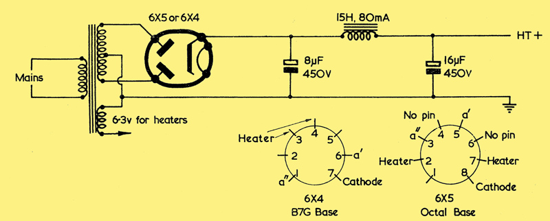
The power pack can be quite conventional, and a suitable circuit is shown. The rectifier may conveniently be an octal 6X5 or a miniature 6X4, as these valves work from the same heater supply as the amplifier itself. There is, of course, no objection to using one of the other types of rectifier valve (80, 5Z4, 5Y3, etc.) if an appropriate heater supply is available. The HT secondary winding of the transformer should be about 300/0/300 Volts at 80 mA. The heater current is very slightly over 1 Amp at 6.3 Volts and the HT current required for the amplifier is about 60 mA.
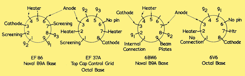
Valve Base Connections
|