|
There is always a keen interest amongst readers in audio amplifiers and, because of this, such amplifiers have been the subject of several Suggested Circuit articles over the past few years. The circuit discussed in this months contribution is also that of an AF amplifier, and it should be of especial interest to those constructors who require a unit capable of delivering a high power output without the use of expensive and critical components.
The amplifier described here provides an output of 9 Watts. It requires only three valves, one of which is the HT rectifier, a considerable economy having been effected by the use of two triode-pentodes in the AF stages. Few of the components are in any way critical. The amplifier is intended to be used with a crystal pick-up and it could be installed, with the gram motor-board, in one of the larger record player cabinets currently available. There are three controls, these varying volume, treble and bass response. A small degree of negative feedback is incorporated, this allowing bass boost to be obtained in the amplifier stages which follow the tone controls.
It was decided to specify a mains transformer instead of employing an AC/C power supply arrangement in order to overcome the difficulties which arise with the latter. Such difficulties consist mainly of the necessity of avoiding hum and excessive heat dissipation, and of guarding against shock. With the power supply circuit shown here the amplifier chassis is completely isolated from the mains and may be bonded direct to the frame of the gram motor-board. The mains transformer required need not be excessively large in physical size nor heavy in weight, and suitable types are available through the usual channels at reasonable cost.
It should be pointed out that this amplifier is not claimed to fall into the true hi-fi category. Nevertheless, it should be capable of offering a performance which is at least as good as that of many commercial record player amplifiers having push-pull output.
The Circuit
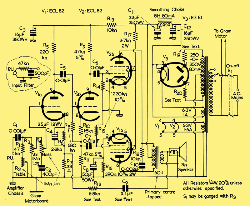
Full circuit of the amplifier
The pick-up employed with the amplifier connects into the tone and volume control circuit offered by C1, R1, R2, R3, R4 and C2. The slider of the last potentiometer in the circuit, R4, connects direct to the grid of V1(a). V1(a) is a voltage amplifier triode, and the signal on its anode is passed, via C5, to the grid of the phase-splitter, V2(a). V1(a) and V2(a) are the triode sections of the two triode-pentode valves employed in the circuit. Equal signals of opposing phase appear across the anode and cathode loads, R9 and R11, of V2(a), and these are applied, via C5 and C7, to the grids of the output pentode V2(b) and V1(b). The pentodes operate in push-pull, their anodes feeding into the centre-tapped speaker transformer primary in normal manner. A small degree of feedback from the speaker transformer secondary to the cathode of V1(a) is obtained via C9 and R12. C9 causes feedback at the lower frequencies to be less than occurs at middle and high frequencies, thereby providing a measure of bass boost.
The power unit circuit is quite conventional, a mains transformer having a centre-tapped HT secondary feeding the full-wave rectifier, V3. A relatively low inductance choke provides smoothing after the reservoir capacitor, C12. Further smoothing, for V1(a) and V2(a), is given by R13 and C3.
Design Points
There are several design points which need to be discussed.
The rectifier specified in the V3 position is an EZ81, this having been chosen because it is of 'all-glass' construction and, therefore, fits in comfortably with a layout employing two ECL82s. However, any other rectifier capable of operating from a 250-0-250 volt HT secondary at a rectified current of 80 mA may be employed in place of the EZ81, should this be desired. Alternate rectifiers may, of course, have heater voltage and current requirements other than these noted in the diagram for the EZ81.
If the EZ81 is employed it should, under the conditions in which it is used in the circuit, have a minimum limiting resistance for each anode of 150Ω. In the diagram limiting resistors are shown as R19 and R20. In practice, mains transformer losses including winding resistances, will provide much, if not all, of the limiting resistance required. A satisfactory approach in this particular instance would consist of measuring the DC resistance of each half of the HT secondary winding of the transformer employed and, if this is below 150Ω, inserting resistors in the R19 and R20 positions having values which would make the total resistance up to this figure. Thus, if it is found that each half of the HT secondary has a resistance of 120Ω, then R19 and R20 may be given values of 30Ω. For values of 50Ω and below, R19 and R20 should preferably have a rating of 1 Watt, above 50Ω they should have a rating of 2 Watts. Should the DC resistance of each half of the HT secondary be greater than 150Ω R19 and R20 are not needed, and the outside terminals of the winding may be connected direct to the anodes of V3
It will be noted that R18 and C10, connected across the primary of the speaker transformer, provide top-cut and that they appear inside the feedback loop. It is, theoretically, an undesirable practice to have a top-cut circuit inside the feedback loop; but this is often done in commercial amplifiers of the class under consideration here and in which the level of feedback is low. If it is so wished the constructor may, after the amplifier has been completed, experimentally determine whether in his particular case these two components are needed. It will probably be found that they give a small but noticeable improvement to the overall response.
The speaker transformer employed should be capable of passing a current of 30 mA in each half of its primary winding.
Negative Feedback
After the amplifier has been completed it should be initially tried out without the negative feedback loop connected. The feedback loop may be broken by opening the circuit between C9 and the speaker transformer secondary. If, when C9 is connected up after initial tests it happens that the voltage from the speaker transformer secondary is in incorrect phase, positive feedback will occur, resulting in a heavy oscillation which may damage the speaker. In consequence, C9 should be connected up whilst the amplifier is switched off, the speaker being protected by connecting a resistor of some 20Ω in series with it. The amplifier may then be switched on. If there is evidence of oscillation, audible as a loud howl from the speaker, the amplifier should be switched off again immediately. The connections to the speaker transformer secondary should then be reversed, whereupon the phase should be such that correct negative feedback takes place.
The degree of feedback allowable in the amplifier depends to a large extent upon the quality of the speaker transformer. Too high a feedback level will cause oscillation. Such oscillation may be differentiated from the loud howl given in the positive feedback instance just described because it will probably occur at a supersonic frequency, making itself evident in the form of a hiss, or of distortion on transients. The value specified for R12 should be sufficiently high to obviate this possibility. R12 may, nevertheless, be increased in value if it is felt that the feedback level is too high. The value of C9 may be experimentally altered, if desired, to vary the degree of bass boost offered in the amplifier.
Final Points
Little else needs to be said about the amplifier since it is very simple and straight forward in design. There should be few difficulties in layout, provided that the normal precautions are taken. The tone and volume control components in the grid circuit of V1 are liable to pick up hum and, if S1 is ganged with the volume control R3, care should be taken to see that the mains wiring to the switch does not approach these components too closely.
It is possible for R2, R3 and R4, together with the components immediately connected to them, to be mounted on a small metal panel separate from the main chassis. If this course is adopted the connection to the grid of V1(a) should be made via screened cable, the screening being used to bond together the metal panel and the amplifier chassis.
It may be found that some pick-ups cause reproduction to have an excess of treble. Should this occur a top-cut filter may be connected between the pick-up and the input terminals of the amplifier. A suitable filter is shown in the inset.
|