|
The data provided by valve manufacturers states that valves must not be operated under such conditions that the resistance between the control grid and cathode exceeds a certain specified maximum value which varies from valve to valve. This implies that valve grids must never be left unconnected, but they can, of course, be connected to earth (either directly or through a coil) when cathode bias is employed.
It is often desirable to use a very large value of grid resistor (Rg) in order to avoid loading the previous stage. If the maximum value quoted in the valve data for Rg is used, the resulting loading of the previous stage may be enough to cause appreciable loss of gain.
It is often stated in elementary text-books that if the control grid of a valve is biased so that it is negative with respect to the cathode, then no current whatsoever will flow in the grid circuit. If this is true no direct current will flow through Rg, no steady voltage will be developed across it and this resistor will merely allow the valuable signal to be attenuated. What possible reason can there be, then, for not using a much larger value for Rg to prevent this attenuation? In order to answer this question we must abandon the idea that no current flows in the grid circuit and take notice of currents of fractions of a microamp.
Grid Characteristics
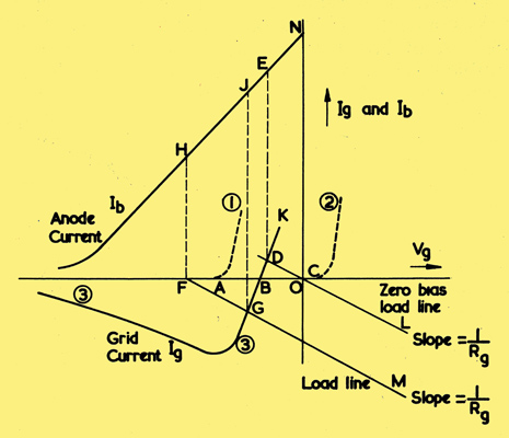
Fig. 1. Grid characteristics plotted with the mutual characteristic Ib.
As the grid of a valve becomes less negative, a point is reached (A in Fig. 1) where the grid acts as an anode and electrons flow to it from the cathode. This grid current increases rapidly as the grid becomes more positive (curve 1). In a practical circuit the electrons flow from the grid through Rg and back to the cathode. The cathode resistor is normally much smaller than Rg and therefore this flow of grid current causes the grid to become more negative by an amount which is approximately igRg volts. Leaky grid detectors and most oscillators are biased by a voltage developed in this way. Grid current flowing in this direction is said to be positive grid current.
Curve 1, for a typical indirectly heated valve without the slightest trace of gas in it, shows that positive grid current commences to flow whilst the grid is still negative by the amount OA (of the order of 1 Volt). In the case of perfectly hard directly heated battery valves, however, the positive grid current may not commence until the grid is slightly positive, at point C on curve 2. Such valves are therefore sometimes operated at zero bias.
Reverse Grid Current
Grid current can flow in the opposite direction from that just described and is then known as reverse or negative grid current. There are three possible reasons for negative grid current tending to flow, namely:
- If the valve contains an extremely small amount of gas (as is usually the case), a gas ionization current will flow.
- The grid voltage will normally be negative with respect to that of all other valve electrodes. Any leakage path, including that across the base, will therefore lead to reverse grid current.
- If some of the electron emissive oxide coating from the surface of the cathode passes to the grid, the grid itself will emit electrons when warmed by the heat radiated from the cathode.
The gas current is usually the largest of these three effects, which all tend to make the grid less negative by an amount igRg Volts where ig is the sum of the grid currents due to the three effects.
Total Grid Current
The effects of positive and reverse grid current thus oppose each other, but they cancel out at one particular value of grid voltage. The total net grid current can be represented by curve 3 of Fig. 1 for a typical indirectly heated valve. At grid voltages more negative than point B the negative grid current predominates over the positive grid current, and vice versa to the right of B. For obvious reasons B is known as the grid current cross-over point and no grid current flows when the grid is at the voltage represented by this point. It usually occurs at Vg = -0.5 to -1 Volt for indirectly heated valves. If the valve is operated without any grid connection, no grid current flows and the grid operating point will be at B. There is another possibility, which shall be considered shortly, if the grid characteristic has the shape shown in Fig. 2.
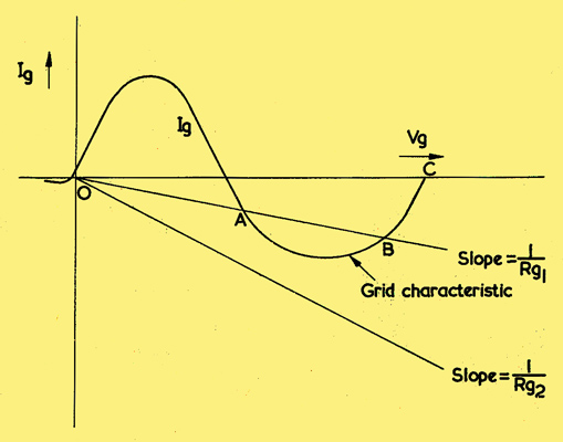
Fig. 2. Grid characteristic of a valve in which grid blocking can occur.
Anode Current
It is useful to plot the mutual characteristic (i.e. anode current/grid voltage) on the same graph -as the grid characteristic; the anode current is then easily determined from the grid operating point. The mutual characteristic is marked Ib in Fig. 1, but as the anode current is measured in milliamps and the, grid current in microamps, the scale used for Ib is different from that used for ig.
Operating Points
If the valve is operated with the grid resistor returned to cathode (i.e. at zero bias), the operating point will be at D. The grid load line passes through 0 when the bias is zero and has a slope of 1/Rg; it cuts the grid characteristic at D. The anode current which flows at zero bias can be found from point E which is vertically above D. Thus the flow of grid current reduces the anode current from point N to point E.
If the valve is biased by a voltage OF so that the anode current would be represented by point H in Fig. 1, the effect of the grid current flow can again be found. The grid load line FGM should be drawn through F to intercept the grid characteristic at G. It can now be seen that the anode current will be increased to point J because of the voltage developed across Rg.
The operating point can thus be moved one way or the other by the grid current flowing through Rg. This change of grid voltage is proportional to the value of Rg. In order to keep the operating point reasonably close to the desired value, an upper limit must be imposed on the value of Rg. This limit depends on the probable grid current (measurement of which is not easy, as its magnitude is of the order of a microamp), as well as on a number of other valve characteristics and on the circuit in which the valve is to be used. It is therefore wise to follow the advice of the valve manufacturers and limit Rg to the recommended value.
The maximum permissible value of the grid resistor must be reduced in proportion if it is common to two or more valves so that their combined grid current flows through it. This situation will usually occur in AGC controlled RF and IF stages where the AGC time constant must also be kept in mind when choosing grid resistor values.
Grid Blocking
When the grid voltage becomes positive, electrons are attracted to it and, under this electron bombardment, the grid may itself emit secondary electrons. This secondary electron current is in the opposite direction to the electron stream from cathode to grid. In some valves it may merely result in a slight change of slope in the positive region of the grid characteristic, but in other valves the net grid current may become negative as shown in Fig. 2. In such a case 'grid blocking' can occur.
Fig. 2 is merely a continuation of the grid characteristic curve from the point K in Fig. 1 into the positive region of grid voltage. Both scales in Fig. 2 are much more compressed than those of Fig. 1. The distance OC represents about 100 Volts and the two peaks represent currents of the order of 1 milliamp.
The grid load line representing the grid resistor Rg1 cuts the characteristic at A. and B in Fig. 2. If the grid voltage (bias plus signal peak) is at any time sufficient to reach A, the operating point will automatically jump to B, as A is unstable. The operating point will then remain at B until the grid resistor is reduced, in. value or the apparatus is switched off. The grid voltage at B will be of the order of +100 Volts; a correspondingly high anode current will tend to flow and the valve is likely to be permanently damaged.
Prevention
Grid blocking can only occur when the load line representing the grid resistor cuts the negative loop of the grid characteristic. Grid blocking cannot occur if the grid resistor is represented by a load line such as the one in Fig. 2 which has a slope of 1/ Rg2 and which does not cut the curve. Rg2 is of lower value than Rgi.
If a valve is used which has the type of grid characteristic shown in Fig. 2, care should be taken to ensure that the grid resistor is low enough in value for the load line not to cut the grid characteristic.
|