|
Abstract
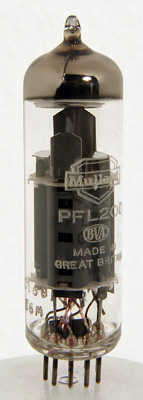
A Mullard PFL200.
Complementary characteristics allow economic full-performance designs.
Developed by Mullard to meet the needs of the latest dual-standard television receivers, the PFL200 is a video valve of unique construction. A novel feature in its design is the use of a 10-pin B10B valve base. This new base - the decal base - makes possible the inclusion of two completely separate pentode systems in one envelope.
The pentodes in PFL200 are dissimilar, and have been given complementary electrical characteristics which make possible the design of exceptionally economic full-performance television receivers. Particular care has been taken in the pinning and in the screening between the two sections of the valve to provide independence of operation.
Characteristics of the PFL200 - Output Section
The PFL200 'L section is designed to operate as a high-gain video output pentode capable of producing a large output voltage across a low-value anode load resistor. To achieve high gain, which also permits the application of negative feedback, a frame-grid control grid has been used, and this gives the valve a slope of 21mA/V at 30mA.
Note has been taken in the design of the 'L section of the increasing popularity of high-level contrast control circuits in which the contrast-control potentiometer is placed in the anode circuit of the video output valve. Such circuits provide constant drive to the synchronising pulse separator and AGC. system regardless of the setting of the contrast control. The capacitance added to the anode when this technique is employed necessitates the use of a low-value anode load resistor. The PFL2O0 can provide adequate current to produce a composite video output voltage of 100 V peak-to-peak across an anode load as low as 2kΩ.
Care has also been taken in the valve design to permit screen-grid dissipation limits that allow for short-term overloading. This can arise when the UHF tuner in a dual-standard television receiver operating from a signal having negative modulation (BBC2) is switched so that neither video signal nor noise is present to provide bias for the grid of the video output valve.
- Amplifier Section
The 'F section of the PFL200 is a voltage-amplifying medium-slope pentode designed mainly for application as a synchronising pulse separator. For this application, the valve has been designed to provide adequate current at a low anode voltage, and care has been taken to reduce to a minimum the feedback capacitance from the anode of the 'F section to other electrodes in the double valve.
Decal Base
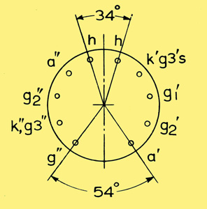
Pin circle diameter = 11.9 mm.
Pin diameter = 1.0 mm.
The drawing above gives the dimensions of the new decal base. It shows that the pitch circle diameter of the B9A 9-pin range of valves has been retained and the 10th pin introduced by bringing the pins slightly closer to each other. Location of the valve in its holder is virtually unaffected and the large gap between pin 1 and pin 10 is sufficiently wide to permit the printing of a wire through into the centre of the valve base on a printed wiring board.
Applications of the PFL200
Video Output Stage and Synchronising Pulse Separator.
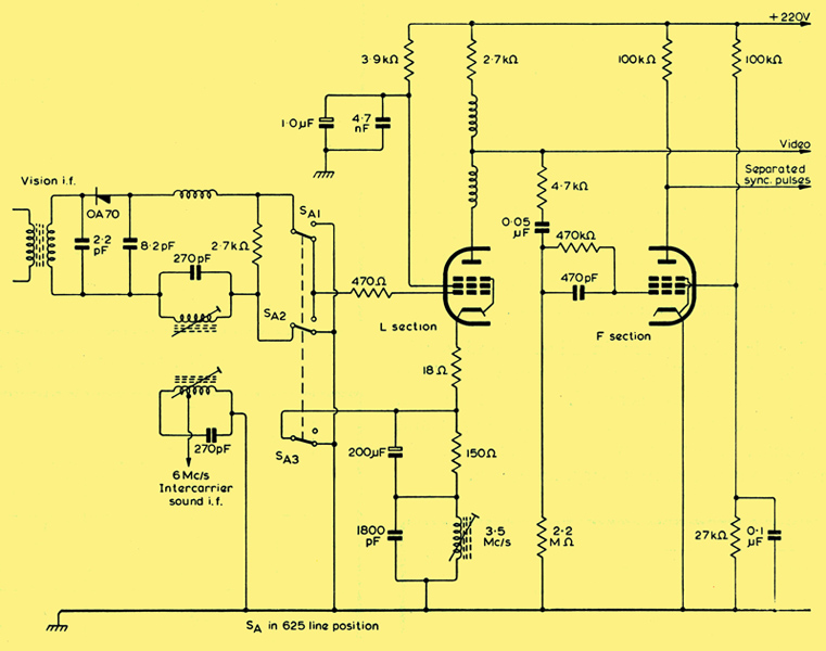
The circuit diagram shows a video output stage and synchronising pulse separator utilising the PFL200. The circuit is intended for dual-standard receivers in the United Kingdom. Where positive modulation is used on VHF and negative modulation is to be used on UHF for these receivers, in contrast to receivers for the Continent, where negative modulation is used on VHF, interference gating is thought to be unnecessary, and the use of a pentode synchronising separator close to the video output valve is then preferable. Consequently, the double-pentode construction of the PFL200 affords a ready means of effecting the convenient combination of video output stage synchronising pulse separator shown above.
The 'L section of the PFL200 is used as the video output stage and the 'F section as the separator. The 'F section has been designed to give a relatively high anode current at a low anode voltage. Because of this, it has been possible to make the impedance of the separator anode circuit relatively low, which maintains a good synchronising pulse waveform. The short grid base necessary to provide good synchronising pulse separation under poor signal conditions is achieved by the use of a screen-grid voltage of about 40V. At the input of the separator, a double-time-constant CR network is used. The parallel network (470pF, 470kΩ) discriminates against hum and IF disturbances of the video Waveform.
Video Output Stage using High-Level Contrast Control.
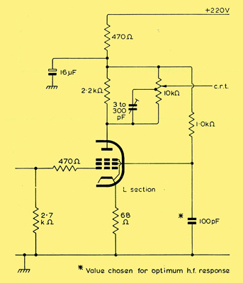
In the diagram above the 'L section of the PFL200 is used as a video output stage with a high-level contrast control. The output section of the valve is designed to accommodate the large shunt capacitances that occur when a contrast control is incorporated in the anode circuit. It is capable of providing a signal current swing of 50mA and thus a peak-to-peak output voltage of 100V across a 2kΩ anode load.
Some resistance in the cathode circuit is desirable to prevent operation of the valve too close to its positive grid region on minimum signals (peak with negative modulation). Under such a condition the flow of grid current could load the video detector and distort the signal. The high mutual conductance of the valve enables adequate stage gain to be achieved when a cathode resistor is used, even with a 2kΩ anode load. The cathode resistor also assists in controlling the no-signal operating conditions as well as providing means for HF compensation.
A resistor is also necessary in the screen-grid circuit to prevent the screen-grid dissipation exceeding the limit under no-signal conditions. To retain the DC component of the signal, this resistor should be de-coupled, and its value should be chosen in conjunction with that of the cathode resistor to establish the desired stage gain. In the diagram above the values of the cathode and screen-grid resistors are 68Ω and 1kΩ respectively.
|