|
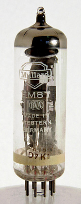
The Mullard EM87.
In many present-day tape recorders, the recording output voltage available for driving the voltage-level indicator is about 10V, which is often insufficient to close the display of existing types of indicator. For this reason, Mullard have designed a new indicator - the EM87 - which has a grid base of only 10V.
An additional feature of the EM87 is that a recording signal greater than 10V will cause the luminous areas of the display to overlap, thus giving a brighter section at the centre of the display. These large voltages can result in distorted recordings, and the brighter section of the display thus serves as a useful indication of when the recording signal modulation is excessive.
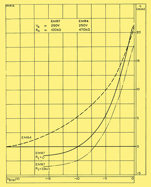
Fig. 1 - Control characteristics: variations of display length with control-grid voltage.
These features are illustrated in Fig. 1, in which the control characteristic of the EM87 is shown. The intersection of the full curve with the horizontal axis shows the control-grid voltage at which the separation L between the luminous areas of the display is zero - that is, the voltage at which the display closes.
The excursion of the line below the horizontal axis indicates the overlapping of the luminous areas at recording signals in excess of 10V. At a target voltage of 250V, the overlap will be 1-5mm for an input of 15V.
The broken line in Fig. 1 in the control characteristic of the EM84 - the previously recommended Mullard voltage indicator. The grid base of this type is seen to be 22V.
Construction
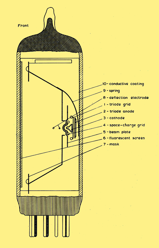
Fig. 2 - Construction of EM87.
The electrode structure of the new valve is shown in Fig. 2. The triode section is to the rear of the cathode, and the indicator section is in front of it.
The specially shaped cathode (3), 10mm long and coated on both surfaces, is mounted horizontally between two micas. Behind the cathode is the grid (1) and anode (2) of the triode section.
A space-charge grid (4) is mounted immediately in front of the cathode, and is connected to the cathode. The space charge formed at this grid promotes a more uniform flow of electrons to the fluorescent screen or target (6). Next to the grid, and also maintained at cathode potential, is the beam plate (5). A slit in this plate ensures that the edges of the fluorescent display are sharp.
The deflection electrode (8) is situated in front of the slit in the beam plate. This electrode consists of two horizontal rods which are taken out to a base pin.
The mask (7), which is normally connected to the HT line, serves to limit the size of the display on the fluorescent screen. A spring (9) on the mask assembly makes contact with a conductive coating (10) of stannic oxide on the inside of the bulb, and this coating is in contact with the fluorescent screen.
Operation
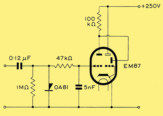
A typical circuit.
In a typical circuit (see Fig. 3) the deflection electrode is connected directly to the anode of the triode. With no signal, the current in the triode load is large, and the voltage of the deflection electrode is therefore about 50V. The electrode is thus about 200V negative with respect to the screen, which is at the HT line voltage. The electron beam is thus caused to diverge widely, and the display is fully open.
When a signal is applied to the triode grid, the load current falls, the anode voltage rises, and the deflection electrode becomes less negative with respect to the screen. The divergence of the beam is therefore less, and the display is partially closed. When the input is 10V, the display is fully closed.
Load Resistance
The deflection-electrode potential of the EM87 is always positive, so that part of the electron stream to the target is intercepted by it and forms the deflection-electrode current. Thus, the current flowing in the load resistor in Fig. 3 has two parts: the anode current of the triode section, and the deflection-electrode current. The ratio of these two parts depends on the value of the load resistance used - the higher the resistance the greater the contribution of the deflection-electrode current, and hence the greater the dependence of the closing voltage on this part.
The electron beam impinging on the deflection electrode gives rise to secondary-emission electrons, and at certain voltages, some of these travel from the electrode to the target, thus reducing the deflection-electrode current. Because of this dependence on secondary emission, the current/voltage characteristic of the deflection electrode will vary considerably from one EM87 to another. Thus in Fig. 3, if the load current contains a high proportion of deflection-electrode current, the closing voltage may be quite different for different EM87.
To reduce this variation in closing voltage, it is necessary therefore to reduce its dependence on the deflection-electrode part of the load current, and for this reason, the EM87 is designed for operation with a load resistance of only 100kΩ. With this value, the anode-current part of the load current at the closing point is several times as great as the deflection-electrode component. The closing voltage is thus determined primarily by the triode characteristics of the EM87, and will change very little from valve to valve.
The low value of load resistance necessitates high values of amplification factor and mutual conductance in the triode section of the valve to produce sufficient voltage gain to drive the indicator section. The amplification factor of the EM87 is about four times that of the EM84 (which was designed to operate with a load resistance of 470kΩ) and the mutual conductance is about 1-5 times as large.
Increased Sensitivity
A typical circuit for the EM87 is given in Fig. 3. With the circuit values given in the figure, the display of the EM87 closes with a peak input voltage of 10V, and an overlap in the display of 1-5mm occurs at an input voltage of 15V.
The target voltage in Fig. 3 is 250V. A shorter grid base can be obtained if the target voltage is reduced by connecting a resistor in series with the target. This therefore provides a simple means of increasing the sensitivity of the EM87. The effect of including a 33kΩ resistor between the target and the HT line is shown as the chain-dot line in Fig. 1. The closing voltage is reduced to approximately 7V, and a greater overlap for voltages greater than this is indicated.
A reduction in target voltage results in a loss of brightness. With the reduction obtained with the 33kΩ resistor, the loss of brightness is not serious, but to maintain a satisfactory level of brightness, the target voltage should not be reduced below 170V.
Other methods of increasing the sensitivity of the EM87 are possible, but these necessarily sacrifice qualities of the valve such as the sharpness of the display, or involve greater complexity of the circuit. However, when used in the simple circuit of Fig. 3, the new Mullard voltage-level indicator will fulfil the sensitivity requirements of most present-day tape recorders, and give also the facility of an indication of signal over-loading.
|