|
A new explanation for apparent deterioration - and a remedy.
It is generally supposed that the lives of oxide coated cathodes are only moderate; it may therefore come as a surprise that, in an investigation of the life records of repeater valves made by Standard Telephones and Cables, no evidence could be found to put a definite term to the cathode lives. The conclusion seems to be that the emission continues indefinitely.2
However, an effect has been found that could easily be mistaken for a drop in the emissivity. This is the formation of a resistive barrier between the cathode core and the coating, which causes a feedback and thereby a change in the measured characteristics. The effect seems to occur so universally that the study of cathode life almost becomes a study of this resistance. When the life history of a valve shows a deterioration in working current, bias, or mutual conductance, it is perfectly feasible to postulate such a cathode resistance of sufficient magnitude to explain the change. If this be done, one would expect the required resistance to be inversely proportional to the cathode area.
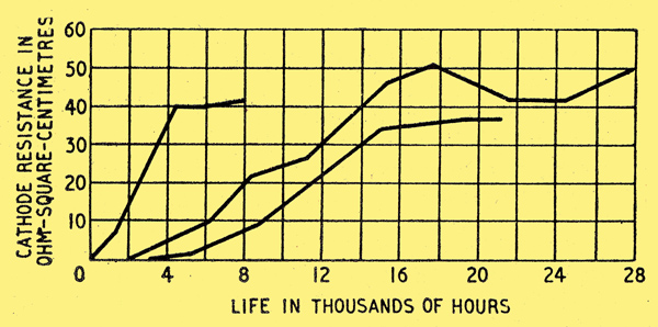
Fig. 1. Growth of cathode resistance during life for three types of valves.
In Fig. 1 is shown, the life history of three valve types in terms of such a cathode resistance. The resistance is brought on to a common basis, i.e., for a cathode area of one square centimetre, and is derived from the observed change of mutual conductance during life. Two of the types are small RF pentodes and the third is an RF pentode of somewhat greater rating - it has a 5-W cathode (triple-carbonate on O nickel) and a mutual conductance of 6.5 mA/V at its usual working anode current of 38 mA. All three can be regarded as normal receiving-type valves.
It will be seen that the resistance builds up to a saturation value of about 40 Ω-square-centimetres for all three types, with a surprisingly sharp angle where the rise meets the saturation level.
The resistance grows in a similar way for many other types; the three valves shown have been chosen because it happens that the tests have been continued long enough to show the saturation level clearly. All the life histories that have been examined can be explained by the hypothesis that a cathode resistance builds up to 40 Ω-square-centimetres and then stays constant.
It is important to realize that the suggestion is that no change takes place in the emissivity of the cathodes, but that in all valves the resistance grows to a certain value and then stays constant. It may, or may not, change the measured characteristics appreciably, according to the design of the valve. But all valves grow the resistance and then stay without change indefinitely.
Are there any reasons for supposing that such a resistance exists physically?
A way of detecting it is to measure the mutual conductance at a high frequency (greater than about 5 MHz) as well as at a low frequency (less than about 50 kHz). With a new valve, there is no difference but with an aged valve the high-frequency mutual conductance is the greater. Such a difference is only to be explained by a resistance shunted by a capacitance having been formed at the cathode.
The double-frequency method has been used to measure the cathode resistance of a number of valves that had deteriorated during life, supposedly for a drop in emission. In every case, a resistance was found and the resistance was approximately that required to explain the change in characteristics.
Growth of Cathode Resistance
Two possible. causes have been suggested for the growth of the resistance: a mechanical theory by Raudorf and a chemical theory by Eisenstein.
Raudorfs - theory3 is that with age the coating shrinks away from the core, leaving contact between coating and core only at minute discrete spots. The reduction of contact area explains the resistance, which is localized round the contacts, and the high capacitance is explained by the close spacing between the core and the body of the coating. Raudorf associated the shrinking of the coating with a network of fine cracks that he observed on the outer surface of the coating of aged cathodes, and stated that he found flat cathodes much superior to round cathodes.
Eisenstein's theory's4 is that a resistive film is formed at the interface of core and coating by the formation of compounds of barium and core impurities. These impurities are deliberately included in the core metal as reducing agents to promote activation: the most usual are silicon and magnesium and their effect is to release tree barium. Eisenstein regards barium-orthosilicate as the most important cause of the resistance.
To the writer it seems that Eisensteins theory is more probable and contains fewer inconsistencies.
It is doubtful whether the resistance could be cured in the manufacturing process - and in any case every trial experiment would take many thousands of hours to complete, as can be seen from Fig. 1. This being so, it is worth while considering what can be done in the design of apparatus to reduce the effect of the resistance, on the assumption that all present valves have it and all future valves will have it, for an indefinite time ahead.
The known facts can be summed up by saying that within six months to two years running, valves will change from their initial state to a final state in which they have a cathode resistance shunted by a capacitance.
Remedy in Circuit Design
Measurements on valves in their final state suggest average figures of 40 Ω-square-centimetres for the resistance and 0.005 μF per square centimetre for the capacitance. It has been verified that the resistance is linear up to a loading of 40 mA per square centimetre. The resistance is temperature dependent, but as there is little difference between the cathode temperatures of one valve type and another, this need not concern the user.
The user will probably not know the coated area of the cathode of any particular type of valve, but he may estimate it from the rated heater power, on the basis of 3W per square centimetre.
The easiest way to deal with this problem is to concentrate on the two states of the valves: if the apparatus is satisfactory for both states, it seems a fair deduction that it would be satisfactory during the period of growth. The designer may proceed with a trial design, based on the valves in their new state. He then estimates the resistance and capacitance that will grow at each cathode and, by experiment or calculation, tests whether the design is still satisfactory.
It is hardly possible to give very general instructions on how to choose circuits that will prove satisfactory: each case must be considered on its merits. However, consideration suggests that a liberal use of feedback gives the best chance of success. The reason is that the feedback produced by the life-impedance depends on the valves effective mutual conductance and a permanent feedback effectively reduces the mutual conductance. A rough rule is that the permanent feedback should swamp the life-impedance feedback.
Take, first of all, a rather simple case, a single valve used for Class A amplification at high radio frequencies. Since the life-resistance is adequately by-passed by the life-capacitance, it will cause no feedback, but will only alter the bias conditions. This is easily allowed for by using a cathode resistor large compared with the life-resistance to provide bias. This usually gives excess grid bias, so the grid is returned, not to earth, but to a positive point. By this very simple device the valves running conditions can easily be kept almost the same for its two states.
Now consider an amplifier for audio frequencies. It is not likely that the valves for this service will show particularly large changes during life, as there is little need for a high ratio of mutual conductance to heater power. The feedback due to the life-impedance will be constant over the audio-frequency band. To reduce distortion, it is customary to provide a strong feedback from the output of the amplifier to an early stage and this would probably swamp the life-feedback. It seems likely that little modification would be needed to most audio-frequency amplifiers to make them satisfactory.
It thus seems that where the application involves frequencies either very high or very low there should not be any great trouble. A more difficult case is the video-frequency amplifier, partly because the life-feedback then varies over the band and partly because the valves likely to be used are just those most susceptible to the effect.
Such amplifiers are normally required to have a flat frequency characteristic, and it is therefore necessary to compensate for their natural tendency to fall off at the higher frequencies. This is often done by increasing the effectiveness of the inter-stage coupling at the higher frequencies, but another way is to provide a frequency-dependent feedback, and this seems a better way for our present purpose.
Considering a single stage, the compensating feedback may be a resistance and capacitance in shunt in the cathode lead. Now there is usually a range of feedback for which the overall result is much the same, i.e., the same stage gain and frequency characteristic can be got by using high forward gain and high feedback or low forward gain and low feedback. It may thus be possible to swamp the life-feedback. Where there are a number of stages, it must be considered whether to use feedback over several stages, at each stage, or a combination of both.
If great linearity is required in the input-output voltage characteristic, then feedback will be needed for this purpose. Such a requirement arises in multi-channel carrier amplifiers. For this case, it may prove best to use frequency-dependent feedback at each stage and frequency-constant feedback over the whole chain.
References
- Standard Telephones and Cables
- C C Eaglesfield, Electrical Communication, June 1951, pp 95-102.
- W Raudorf, Wireless Engineer, October, 1949, pp 331-337.
- A Eisenstein, Wireless Engineer, March 1950, pp 100-101.
|