|
Why High-Frequency Currents Tend to Flow on the Outside of Conductors.
In connection with microwave valves, two months ago, I happened to mention that at such high frequencies it was better to use sheet than wire, because most of the current flowed at the surface-a peculiarity known as skin effect. With such a picturesque name, it could hardly fail to be known. But I wonder if it is understood. I suspect that many reasonably knowledgeable technical people regard it as one of the sweet mysteries of RF life that are better not inquired into too closely. There is some excuse for this attitude, because the books that do deal with it thoroughly make very heavy mathematical weather of it, full of special Bessel functions, wave propagation, and such like. Consequently the simpler treatises tend to laugh it off by hinting that you must be a fool if you cant see that it is in the nature of very high-frequency currents to keep to the surface. The thing is 'skin effect', so - well, there you are!
For those who are not honours graduates (and some of us who are -ed.), but nevertheless have inquiring minds, some of the books strike a happy medium. But the said inquiring minds may perhaps be a little troubled by the fact that several apparently quite different explanations of skin effect exist. There is, however, no cause for alarm; skin effect is one of those things that can be approached by different routes; some people may find one way easier, some another.
Basic Principles
Personally I think the best starting point for any expedition of this kind is with the basic principles of electricity. A bit more thought may be needed to work it out from there, but every time one does it makes those principles clearer in the mind. However, there is no reason against - in fact every reason for - supplementing this approach by views from other positions, which, although established from fundamentals indirectly, may be more familiar in practical work. For instance, one way of explaining skin effect is in terms of eddy currents. To anyone who has studied eddy currents and knows all about them, this may be a convenient short cut; but if ones understanding of eddy currents is itself rather shaky it is clearly not a sound proposition.
The simplest conductor to consider is a long straight round-section wire made of a non-magnetic material, say copper, and far enough away from other conductors for their effects to be neglected. When DC flows it does so uniformly over the cross-section, so that if the wire were imagined to be divided up into equal thick parallel strands each would be carrying the same current. Since each strand has the same emf between its ends and the same resistance, it could hardly be otherwise. What calls for some explanation is the fact that with AC it is otherwise. If the frequency is sufficiently high, the strands around the circumference are found to be carrying nearly all the current, and those in the middle hardly any. Consequently the resistance of the wire as a whole is higher for AC than for DC.
Students of the elementary books that try (regrettably) to make things easier by introducing reactance as a kind of resistance may need to be assured that this increase in resistance is quite apart from the increase in impedance due to the inductance of the wire as a whole. Such an assurance may be especially necessary because inductance does come prominently into my explanation. But not the inductance of the wire as a whole. May I emphasize, then, that there is an increase in actual resistance of the wire when the current becomes unevenly distributed from any cause whatever, whether by making the current alternate or by substituting Eureka for some of the copper.
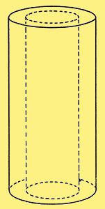
Fig. 1. A short sample (highly magnified) of a long solid wire, divided longitudinally by imaginary boundaries into two 'strands', one inside the other, having equal cross-sectional area.
Presumably it is obvious that the resistance of a wire is greater if current ceases to flow altogether through some portion of its cross-section, because that is the same thing as making the wire narrower. But anyone who does not find it obvious that any departure from uniform distribution of current flow increases the resistance should try calculating the total power dissipated in two parallel resistors when a given total current is shared between them in various proportions. Suppose, for example, that the resistors are each 10Ω, representing (say) the core and outer parts of a 5Ω length of wire (Fig. 1) and that the total current is 4 Amps. If this is shared equally, each path takes 2 A and the power dissipated in it (I2R) is 22 x 10 = 40 Watts: total for both paths 80 Watts. Now suppose one path takes 3 A and the other 1 A. Dissipation in the 3 A path is 90 Watts and in the other 10 W; total 100 W. Of course the voltages across the two paths are now unequal (assuming the current is DC), which is impossible if the paths are in parallel. But not with AC For if the low-current path has more inductance in series with its resistance than the other path, it is quite possible for the voltage across it to be the same as across the other.
But, you may say, surely all strands of a single wire have the same inductance, especially if (as we are supposing) the division of the wire into strands is only imaginary? Even when one takes two separate wires with which to wind a coil, if they are twisted together throughout their length the inductive coupling between them is very nearly 100%; any difference between two longitudinal halves of a single wire must be quite negligible! Regarding the inner and outer parts of the wire as separate strands, with boundaries as in Fig. 1, they obviously have the same length (and, if wound into , a coil, the same number of turns), so assuming 100% coupling between them they could be represented electrically as in Fig. 2.
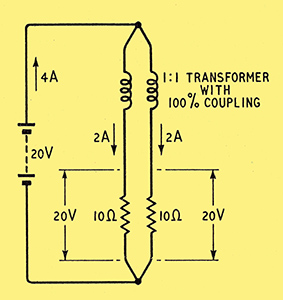
Fig. 2. If the resistance of the wire is taken as 5 Ω, the two 'strands' can be represented by two 10 Ω resistances in parallel. Their inductances are also in parallel and very closely coupled; on the assumption that they are equal they are shown as making up a 1:1 transformer. At zero frequency the inductance has no effect, and an emf of 20 Volts is sufficient to maintain a current of 4 Amps, divided equally between the strands.
At zero frequency the inductance would have no effect, so only the lower part of the diagram would apply, and the emf to pass 4 A (2 A through each path) would have to be 20 V. Since the wire is supposed to be stretched out straight, its inductance would presumably be quite small, so the DC conditions would not be much affected if the emf alternated at a low frequency, say 50 Hz. Very little more than 20 V would be needed to maintain the total current at 4A. At high frequencies, however, the back emf generated by the flux set up by the current would become appreciable compared with 20 V, and a greater generator voltage would be needed to maintain the current. At a sufficiently high frequency, the inductance would become the dominating partner, swamping the resistance. But on the assumption of equal inductance and 100% coupling, the impedances of the two strands would be equal, whatever the frequency, so the currents in them would remain equal.
But now let us see if this representation - which at first sight might seem to be at least a close enough approximation to the truth - is justified. And this is where we get down to the bedrock of basic principles. One of the most important of them is that the magnetomotive force around any loop is proportional to the current enclosed (or linked). In the MKS system it is actually equal to the number of ampere-turns; in the cgs system it is 0.4 π times the amp-turns. Our wire, being straight, has only one 'turn', so the mmf around any loop embracing it when it is carrying 4 A is (in the MKS system) numerically equal to 4, or, in the cgs system, 5.03. The path of the magnetic field at any point caused by current in a straight wire is a coaxial circle, and its strength is equal to the mmf divided by the circumference of the circle. So just outside the wire, around its surface, the field strength (H) is mmf πD, where D is the diameter of the wire. If D is, say 0.4 cm, H due to 4 A is 4 Oersteds. The flux density B is equal to H multiplied by the permeability, μ, and in the cgs system the μ for air is practically 1; so in our example B would be 4 Gauss (or lines per sq. cm). In the MKS system it would work out at 0.0004 Weber. But for our present purpose numerical values are only of incidental interest, so there is no need to worry about systems of units - they do not affect the basic facts, namely, that the mmf is the same in every concentric path around the wire, because all enclose the same current, and the field strength and flux density are therefore inversely proportional to the diameter, as shown in Fig. 3.
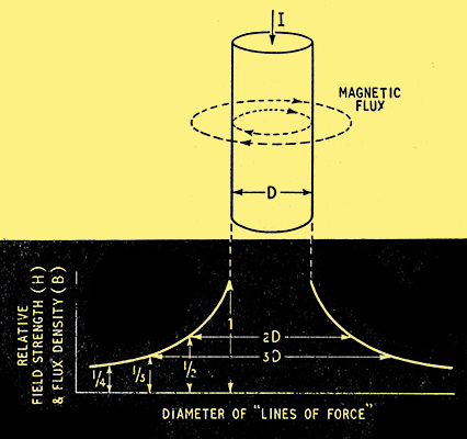
Fig. 3. The density or magnetic flux paths (lines of force), two of which are shown around the wire, falls off inversely as their length (which is proportional to their diameter) as shown in the lower part of the diagram. D is the diameter of the wire.
The same principles apply inside the wire itself, but of course we have to allow for the fact that the current enclosed, and therefore the mmf, progressively diminishes as the diameter of the path is reduced. The current, uniform distribution being assumed, is proportional to the cross-sectional area, and therefore to the square of the diameter. So the field, being proportional to the diameter squared, divided by the diameter, is simply proportional to the diameter and we can complete the field/diameter diagram as in Fig. 4.
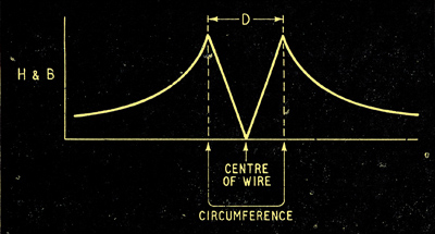
Fig. 4. To the field and flux density diagram for the field outside the wire is here added the portion applying to the field inside the wire, assuming the current is uniformly distributed. This diagram takes no account of the sign (direction) of the field.
The one essential thing to grasp out of all this is that current flowing down the centre of the wire is linked with more flux than current in the outer 'skin'. The difference is the flux in the wire itself; this flux is proportional to the total current through the wire, but is independent of its gauge. This may seem rather surprising, but if you remember that the maximum flux density (which is at the surface of the metal) is inversely proportional to D, while the area through which it passes is directly proportional to D, you will see that D cancels out when calculating flux = flux density x area.
Now if the current is alternating, the whole of the flux it produces is alternating, and therefore is inducing an emf in the wire. Other things being equal - frequency and length of wire - the emf induced is proportional to the peak flux. Since, as Fig. 4 shows, the flux linked with the core of the wire is greater than that linked with the skin, we see that more emf is induced in the core than in the skin. But the generator emf applied across all strands of the wire is the same, so after the induced emf's have been deducted there is less to spare for driving current through the resistance of the core than through the resistance of the skin. Consequently the effect of the unequal flux is to divert current from the core to the skin, and the resistance of the wire as a whole is increased.
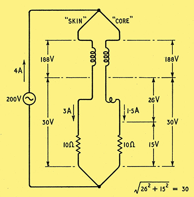
Fig. 5. This is Fig. 2 modified to apply to a frequency high enough for the reactance of the wire to be greater than its resistance. The fact that (as shown in Fig. 4) there is more flux outside the core of the wire, linked with it, than there is outside the skin, causes the core to have a higher inductance, so that less voltage is left to drive current through its resistance, and less current flows through it.
Using conventional circuit symbols, this state of affairs can be shown as in Fig. 5, where the little extra coil in the 'core' path represents the extra inductance corresponding to the flux inside the wire. The important point is that this inductance is not coupled to the 'skin' path. Its back emf constitutes an extra voltage drop in the core path, and to make the situation clearer some figures are given on the diagram. For comparison with Fig. 2 the generator voltage has been raised sufficiently to maintain the total current at 4 A. The voltages across the two 'windings' of the transformer must be equal and in phase, because the ratio is 1:1 and the coupling 100 per cent, so the voltages across the rest of each path must also be equal. But because of the extra inductance the current in the core path is not only less than the skin current but lags it in phase. In this case the phase difference is nearly 60°, which accounts for the fact that although the current in one branch has gone up by 1 A it has gone down in the other by only 0.5 A. So here is another cause of increased resistance. If you compare Fig. 5 with Fig. 2 you will find that the power dissipated, for the same current, has risen more than 40 per cent, equivalent to a rise in resistance from 5 &Omega to more than 7 Ω. Note that a large diversion of current has been caused by a relatively small difference between the inductances of the two paths.
One result of the diversion of current from the core is to modify Fig. 4. The field outside the wire (being determined only by the total current) remains unchanged, but there is less inside. This tends to reduce the excess of voltage induced in the core. The diversion therefore takes place only so far as is necessary to bring about a balance, such as that shown in Fig. 5. But if the frequency is very high indeed, and the resistance of the wire is very low (as it would be if made of heavy gauge copper), practically the whole of the applied voltage is used in overcoming the inductance. In other words, the voltage induced in all strands of the wire must be practically the same. This cannot happen if some strands are linked with more flux than others, so current ceases altogether except at the surface. Then there is no flux inside the wire and all parts of the wire are linked by the same flux, (i.e., the flux outside the wire). And the resistance of the wire is many times greater than it was. The resistances of the various 'strands' are still the same as before; it is just that fewer of them are being used. Directly the resistance rises so much as to absorb an appreciable part of the voltage applied to the outermost skin, it makes possible a slightly greater induced voltage in the inner layers, which means that some current, though small, can flow there.
The thicker the gauge of the wire, the lower its DC resistance in proportion to its inductance, and the greater the skin effect. This fact sometimes makes unthinking people jump to the conclusion that at very high frequencies a thick wire has a greater resistance than a thin one. Actually, of course, the thick wire has the lower resistance, however far skin effect is developed, for it has more surface. It is true that in proportion to the amount of metal used its resistance is greater, because that goes up as the square of the diameter whereas the surface goes up in simple proportion to the diameter. So to obtain the lowest resistance with a given amount of metal it should be in the form of a thin-walled tube. It is also true that a coil wound with thick wire may have a higher RF resistance than a coil of the same dimensions wound with thinner wire. But if so it is not because of skin effect but because the lower resistance of the thick wire is being more than offset by greater dielectric losses in the insulation between the turns.
A moment or two ago we saw that skin effect brought about a reduction of magnetic flux inside the wire, the flux outside (for a given current) remaining the same. So the total flux produced by a given current is reduced, or in other words the inductance of the wire is reduced. The inductance of any circuit depends to some extent on frequency: it is greatest at zero frequency, when Fig. 4 holds good; it falls as skin effect comes into play; but there is a limit to the fall, for however high the frequency the circuit cannot lose more than all the flux inside the wire, and that is usually quite a small proportion of the whole. So at very high frequencies the inductance curve levels out again, towards a slightly lower figure than the DC value. The more refined formulae for calculating inductance provide a frequency correction.
We have already seen that skin effect is more pronounced with thick solid wire than with thin, in the sense that a given frequency multiplies its resistance by a larger factor, though it never becomes so high as that of the thin wire. It should also have been clear that wire made of low-resistance metal develops skin effect at a lower frequency than high-resistance metal. Study of Fig. 5 shows that the lower the resistance of the wire - whether because it is thick or because it is made of low-resistance material, or both - the lower the frequency at which its inductance is large compared with its resistance, causing the current to crowd towards the skin in order to reduce the internal flux and thus equalize the inductive voltages in all strands. So a thick copper wire shows skin effect at a comparatively low frequency; a thick resistance wire or a thin copper wire is similarly affected only at a much higher frequency; and a thin resistance wire maintains its resistance within close limits up to a much higher frequency still. Finally, a wire made of iron or other magnetic material, though higher in resistance than copper and therefore less subject to skin effect, has an enormously higher permeability than copper, so the internal flux is multiplied accordingly, and the net skin effect is far greater even than with copper.
Skin effect is therefore increased by the following: conductance per unit length, permeability, and frequency. The exact calculation of the increase in resistance is, as I said, a matter for the brighter mathematicians, and practical people like ourselves fall back on tables or graphs. While it is easy enough to use these to find the increase for an infinitely long straight wire with no other conductors anywhere near, no real circuit answers to that description. Even if one takes a practical view of 'infinitely long' (in some circumstances a foot or so may be indistinguishable from infinitely long) there must be a return path somewhere if there is to be any current. However, if this is outside the more intense parts of the wires magnetic field, it can be disregarded for purposes of calculating skin effect. But most often one is interested in RF resistance as it affects coils, transmission lines and other circuits that do not even roughly conform to the above description. Take a coil, for instance. The flux inside the wire forming any of the turns is caused not only by the current in that turn but also by the same current in other turns. So Figs. 3 and 4 do not hold good, and the explanation based on them falls down. But its conclusion does hold good if it is expressed more generally. What we really found was that when the frequency is high enough for the inductance to predominate over resistance in the impedance the current tends to flow where it makes the inductance least. In a straight wire, this is at the circumference of the cross-section; in short, the skin.
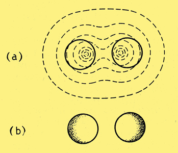
Fig. 6. When two wires carrying the same current are close together, their combined magnetic flux is distributed something like this (a), and the HF current consequently tends to flow where shaded (b).
Fig. 6 shows a section through two adjacent wires carrying current in the same direction. Assuming their returns are relatively far away, the flux pattern will be somewhat as shown at (a). The parts of the wire linked with least flux are those farthest apart, so the greatest current density will be through them, as shown by the shading at (b). This modified distribution is some- times given a separate name, proximity effect, but basically it is the same as skin effect. In a single-layer coil, the tendency is for the current to flow along the inside surfaces of the wire. Abacs for calculating RF resistance of coils are in Radio Data Charts.
Then there is the coaxial line. It is no surprise to learn that current through the inner conductor tends to flow at the outer surface, as in simple skin effect. But it may seem rather contradictory that the current through the outer conductor tends to keep to the inner surface. Yet it follows from the same sort of reasoning as we used for the isolated wire.
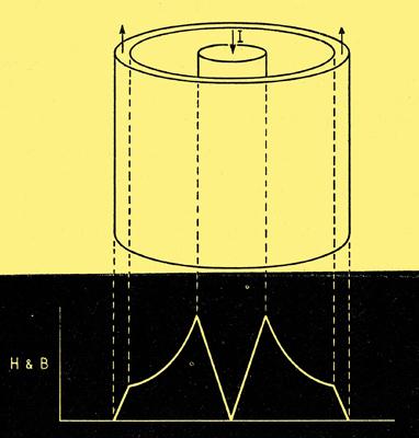
Fig. 7. This is Fig. 4 modified to apply to a coaxial line, where the external field is cancelled out by equal and opposite currents in the two conductors.
If in Fig. 7 we work from the axis outwards, calculating the mmf due to the zero-frequency current enclosed, and dividing by the length of the field path or 'line of force', everything is as before until we reach the inside diameter of the outer conductor. Here we start to enclose a current flowing in the opposite direction, so the net mmf decreases. By the time we reach the outside diameter we are enclosing no net current at all, because the currents in the inner and outer conductors are equal and opposite. So from here outward there is no magnetic field - which of course is one of the advantages of this type of cable. Looking at the possible current paths, we see that a path down the core of the inner conductor, and up the outer skin of the outer, links with all the flux there is, both in the space between the conductors and in the metal, so has maximum inductance. The path of least inductance, and therefore most popular with high-frequency current, is along the surfaces enclosing the space between the conductors.
The only metal having a lower resistivity than copper is silver, so where low RF resistance is worth the extra cost it is customary to silver-plate the surfaces where the current flows. But the resistivity of silver is only about 5 per cent lower, and it has been found1 that plated surfaces are microscopically rough, and the extra distance the current has to go, up and down all these little hills, may more than swallow up the slight advantage.
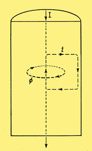
Fig. 8. In this wire, shown in section, the alternating flux (represented by the single line of force, Φ) induces current around paths such as the square one marked. When all such paths are taken into account, the net result is skin effect.
For the sake of anyone who would like an alternative approach to simple skin effect, Fig. 8 shows a longitudinal section of our piece of wire with current flowing down it. Consider any closed path in a vertical plane inside the metal, such as the square one shown dotted. Provided that it is not exactly in the centre, such a conducting loop as linked with some flux, represented by the single coaxial line of force marked Φ. As the current in the wire alternates, so does this flux, which therefore induces an alternating emf around the loop (and around all others like it), and because the loop conducts a current flows around it. According to Lenzs Law, the direction of current must be such as to oppose its cause; so inside the flux loop it must be opposite to the current that set up the flux, which means that nearer the surface of the wire it must be in the same direction as the current there (which was not responsible for the flux). In other words, the current near the axis of the wire is weakened, and the current near the surface is strengthened; in still fewer words - skin effect.
Some time ago, when discussing Energy (January 1952, to be precise) I mentioned that the electrical energy travelling along a resistance-less wire existed solely in the space around, in the form of electric and magnetic fields; it was only in so far as the wire has resistance that energy enters into the wire, there to turn to heat. In saying this I neglected the magnetic field inside the wire, but this was reasonable, for at most it is a small proportion of the whole, and, if a wire really could be devoid of resistance, skin effect would be full developed even at the lowest frequency and there would be no current or flux inside. Supposing now the wire has resistance, energy from the fields must enter it from the outside inwards, being dissipated as it goes. One would expect, therefore, the greatest dissipation to be at the surface, and (since energy must travel at a finite speed) the dissipation nearer the axis of the wire to be not only less intense but also delayed in time. This is exactly what we have already found: the current inside the wire being less, the I2R loss is less than at the surface; and since the inductance is greater it lags in phase.
An interesting point is that when DC is switched on, the magnetic field around the circuit has to grow, so there is a transient skin effect as well as a transient inductive effect, and the current in the wire starts flowing in the skin first and spreads to the inner parts later, before finally becoming uniformly distributed.
The 'strands' we have spoken about hitherto have been distinguished only by imaginary longitudinal boundaries in the solid wire. What if we were to make up the wire of a number of actual separately insulated strands? This idea would occur at once to anyone who viewed skin effect as a manifestation of eddy currents, as in Fig. 8, because the way to minimize eddy currents in iron cores is to break up the current paths by using insulated stampings. It might seem that the insulation of the strands would in the same way interrupt the eddy currents where they pass horizontally from axis to circumference. But in fact these currents do not exist anyway! The current path marked in Fig. 8 is by no means the only one; there is another above it, and its lower horizontal portion carries current equal and opposite to the upper portion of the first, so cancelling it out. And so on for other paths. The only places where the current can be regarded as flowing at right angles to the axis of the wire is at each end (where there must be a conducting path there if the strands are to be electrically in parallel).
So stranding alone does not overcome skin effect. The way to do so is to arrange that equal flux links every strand. This can be done by organizing the strands so that each occupies inside and outside positions in the same proportion. Stranded wire so organized is known as Litzendraht, or more commonly as Litz, and by its use the RF resistance of coils of given dimensions can be considerably reduced. But not only is this wire itself much more expensive than solid, it must be handled carefully and connected with great care and trouble, for if there are short-circuits between some of the strands, or every strand is not soundly connected at the ends and unbroken throughout its length, the result falls considerably short of expectation. In fact, a badly made Litz coil may be even worse than if the wire were solid. The higher the frequency, the more difficult it is to obtain the benefit of Litz, for apart from defects of workmanship the capacitance between strands increasingly nullifies its purpose.
Reference
- Attentuation and Surface Roughness of Electro-plated Waveguides, F A Benson, Proc. IEE, Part III, July, 1953, p. 213.
|