|
Although this design employs only two valves in the amplifier section, it is capable of offering 8 Watts push-pull output for an input signal of the order of 500mV. The amplifier also features an unusual and ingenious treble control circuit.
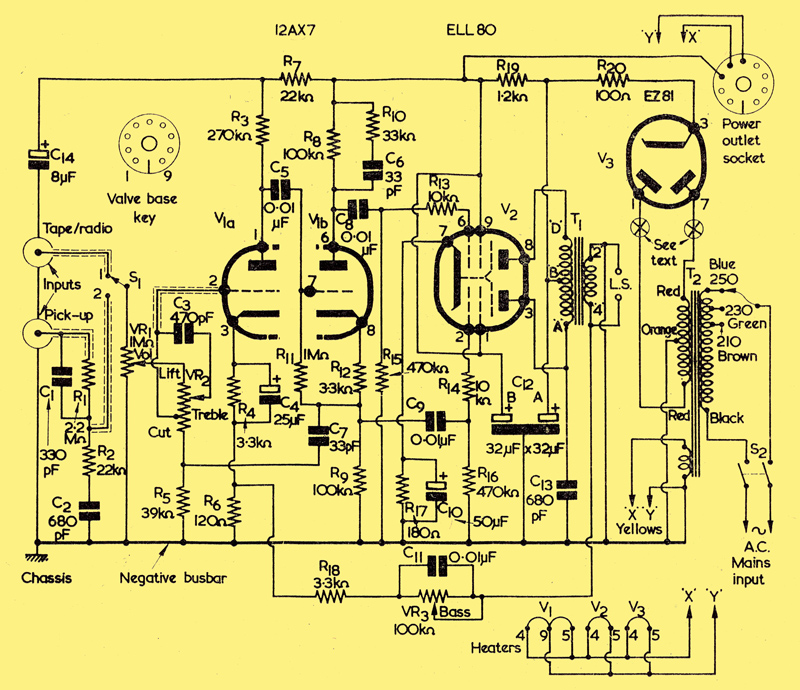
The circuit of the 'Double Two' audio amplifier.
The fairly recently released valve Type ELL80 is a miniature double audio pentode with a common cathode designed primarily for use either in the output stages of stereophonic amplifiers - each section operating in single-ended mode - or as a complete monaural push-pull output stage. Each section has a mutual conductance of 6mA/Volt and anode and screen-grid current demands are modest, these being typically 24 and 4.5mA respectively per section from a 250V supply source. The heater is intended for use in a parallel-connected circuit and operates at 0.55 Amps from 6.3V.
The 3 watts of audio obtainable from a single section might be considered adequate for some applications but is barely comparable with the 8.5 Watts which is given when both sections are utilised in push-pull - which is the system adopted in the audio amplifier design presented here.
One of the benefits derived from the push-pull configuration is the effective suppression of second harmonic distortion, and amplifiers using a push-pull output stage offer the critical ear a discernible silkiness of response which is unobtainable from simple single-ended systems.
The pentodes may be operated in various push-pull modes but Class AB1 is recommended. For an output of 8.5 Watts with 5%, distortion a grid-to-grid input of about 16 Volts RMS is necessary when the recommended anode-anode load is 11,000Ω. To provide adequate amplifier sensitivity a stage of amplification between the input socket(s) and the output stage is essential, and a phase-splitting stage must also be employed to provide the anti-phase voltages.
Fortunately both requirements can be met very simply by employing another 'double' miniature valve, viz., the well-known 12AX7 (ECC83) high-μ double triode, each section of which has a quoted maximum amplification factor of 100. The distortion level can also be lowered at the expense of a little gain by incorporating negative feedback in the amplifier. Some 8 Watts of good quality audio can then be secured from an input of about 500mV, which is adequate for many applications. The amplifier proper may thus contain no more than two 'bottles' (although a rectifier must also be incorporated) and the overall size can be made reasonably small.
The Circuit
The theoretical circuit of the amplifier is shown above. In this diagram, valves V1 and V2 perform the essential audio duties, the additional valve, V3, being the HT rectifier. Two inputs are catered for and either may be selected by means of S1, whilst the output to the loudspeaker is given by a pair of sockets which mate with banana-type plugs. R1 is fitted to provide attenuation and supply adequate loading for modern high output crystal pick-ups, whilst further frequency compensation is effected by C1, C2 and R2. These components can be experimentally adjusted in value to suit the users need if desired.
When S1 is set to position '1' input is direct to the volume control VR1 and, thence, to the treble control VR2. VR2 is a special centre-tapped linear potentiometer of 500kΩ arranged to be ineffective at 1,000 Hz when its slider is at the mid-position.
One half of V1 functions as a voltage amplifier, and gives a stage gain of approximately 60 with the value of anode load resistor specified. Its output is fed to the other half of the valve, where phase-splitting occurs and equal voltages which are opposite in polarity appear in the anode and cathode circuits. Resistors R4 and R12 and capacitor C4 are merely cathode bias components. Bias for the output stage is provided by R17 and C10. Injection of signals from V1(b) into the respective grids of V2 is effected via R13 and R14 and, since these are 'stopper' resistors, one end of each should be soldered directly to the appropriate pin at the valve-holder. It has been found that, without these resistors, trouble is very likely to result due to parasitic oscillations.
The outputs from V2 anodes are combined in T1, and it will be noted that the centre-tap of the primary of this component is fed direct from the un-smoothed HT voltage across C12(a), the remainder fo the circuit being fed via R19 and C12(b). This method of operation not only allows the output valve anodes to receive the maximum available HT voltage, but also permits the use of a relatively low wattage smoothing resistor in the R19 position.
Tone Controls
The treble control is relatively ineffective at 1,000 Hz when its slider is at the mid-position and the input signals reach V1(a) grid via one half of the potentiometer track. If, however, the slider is turned towards 'Lift', C3 becomes operative and high frequencies are passed more readily. If, on the other hand, the slider is rotated towards 'Cut', high frequencies are attenuated due to negative feedback developed across R5 and extracted from the anode circuit via C7. The presence of R5, C7, VR1 and VR2 in the cathode circuit of V1(a) is offset by a compensating network in the anode circuit, and the result is an excellent response at all frequencies.
Making use of components in the degeneration loop is an acceptable way of effecting a degree of bass control. Degeneration is applied to the input valve cathode at the junction of R4 and R6, the feedback being obtained from the output transformer secondary winding via R18, C11 and VR3. The effectiveness of C11 is determinable by the setting chosen for VR3 slider, and bass boosting occurs when this potentiometer is suitably adjusted.
The overall usable frequency response of the prototype, as checked with oscilloscope and audio waveform generators, was in the range 60Hz to 18 kHz, a limit being set to low frequencies by the relatively inexpensive output transformer employed.
A higher grade component here and the use of 0.1μF components for C5, C3 and C9 would undoubtedly extend the low frequency response, but C11 might then also require adjustment.
It should also be appreciated that this is a 'One-Off' design and, as experienced constructors will know, another seemingly identical version might not perform in exactly the same way. No wide differences need be anticipated but whilst one unit might prove completely stable another may give trouble and parasitics might occur. In another version, for instance, C13 might not be needed. Difficulties with regard to instability will probably be due to phase shift in the small output transformer. It could prove helpful, in such instances, to slightly increase the value of R13. -ed.
Power Supply and Voltages
The use of a full-wave indirectly-heated rectifier is recommended as this allows the amplifier valves and those of any associated apparatus connected to the unit to receive a warming-up period without HT voltage. The rectifier valve chosen is the ubiquitous EZ81, which can easily supply up to 350V at 150mA from a 350V RMS supply per anode. The mains transformer is also generously rated and permits some 25 to 30mA to be available at a power output socket fitted to the amplifier chassis. This is adequate for any unpowered VHF or AM tuner and no overloading of the main section is anticipated. The zero signal current drain of the amplifier is 62mA but, with maximum signal, the demand may increase by up to 17%. This fact must be remembered if components with lower ratings are to be used for V3 or T2. If, for example, the power supply socket is omitted, the HT secondary of T2 could be de-rated to 80mA and an EZ80 used in place of the EZ81.
Using the circuit as shown, measured DC voltages should agree approximately with those given in the Table. A high resistance voltmeter should be employed.
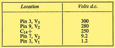
Measured voltages with respect to chassis.
Construction Details
The amplifier proper requires only two valve-holders and if these are carefully orientated wiring up is simplified. The choice of a readily obtainable 5-piece chassis, the sections of which bolt together, further aids construction. Only a few minor items, input and output sockets, tag-strips, etc., are located on the front, rear and side flanges and because of this no drilling details are given for these flanges.
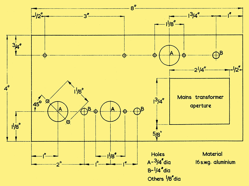
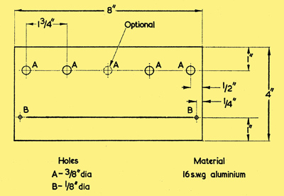
Essential drilling details for the chassis top-plate. Extra holes will be required for mounting C4, C12, the power output socket bracket and the mains transformer, and these may be marked out from the components themselves.
The diagram above shows the main holes required in the top plate. It will be noted that the amplifier proper occupies only one half of the surface, the remaining portion being taken up by the power supply components. The top plate is finally secured to its complementary 2in. deep rectangle of flanges to make a rigid assembly. The diagrams below show the more critical sections of the wiring and the layout above and below chassis.
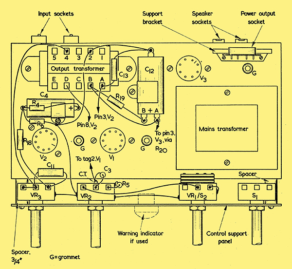
Principal wiring above the chassis. All wiring in the grid circuit of V1(a) should be screened. (The screening is not shown here). This diagram shows the metal covers of the three potentiometers bonded together by wires soldered directly to the cases. If the potentiometers employed have earthing lugs, the earthing wire may be connected to these.
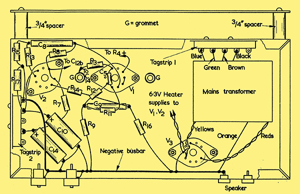
The principal wiring below the chassis.
The panel required is illustrated in detail below. This panel must be held clear of the front of the chassis by at least 0.75in or the on/off switch tags associated with VR1 will foul the mains transformer casing. The spacers are shown clearly in the diagrams above.
The dimensions of the control panel. This is secured to the front section of the chassis with -gin spacers. The centre hole is optional, and is intended for an indicator lamp.
Control knobs are spaced symmetrically along the panel, sufficient space having been left for a warning indicator such as the Bulgin D841/250V (Red, or Transparent Water Clear) Neon Signal Lamp to be fitted centrally if required. The panel will not, however, be visible if the amplifier is housed in an equipment cabinet and is therefore only expected to form a supporting device for the various controls. It may be noted that no room exists for group-board construction, so small items together with the flying leads from T2 are anchored to tag-strips 1 and 2 as shown.
Precautions to be Taken Against Hum
Because mains-derived hum can prove troublesome in high gain audio amplifiers precautions must be taken. For example, all heater wiring must be tightly twisted and kept away from the input circuit. The use of a negative bus-bar to which chassis returns are made is also beneficial and the location of this is clearly indicated in below chassis wiring diagram. Chassis currents are thus kept at minimum. The layout permits very short direct wiring and it is not likely that much improvement can be made in this direction. Valve-holders should be oriented as shown, and all signal-carrying leads associated with the input up to the grid of V1(a) should be made in screened cable, the screening being connected to chassis at both ends of each run. In the prototype there is neither hum nor instability.
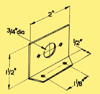
The bracket for the power output socket
If the power output socket is to be fitted it may be either mounted on a small L-shaped bracket as depicted above or it may be built into the chassis rear flange. Fuses could also be provided, but these would be superfluous if a fused mains plug were used.
Checks
A thorough check of all wiring should be made on completion and if all seems in order the valves may be placed in their respective sockets. With the mains plug not inserted in its socket an Ohm-meter should be brought into use to ensure that no direct circuit exists between any tag on tag-strip 1 and chassis but that a low resistance reading is obtainable between any two of the tags. Since the major section of the mains transformer primary winding is between the black and brown lead-outs, this should show a considerably higher resistance than occurs between the brown and green wires or between the green and blue wires. The mains input should, of course, be connected to the lead-out wires which correspond to the mains voltage to be used. The ohm meter negative test should next be clipped to chassis and readings taken from pins 2 and 7 of V1 and pins 2 and 6 of V2; these readings should be high due to the grid resistors. Fairly low readings, corresponding to the resistance in the cathode circuits, should be obtained from pins 3 and 8, V1 and pin 7, V2. Low readings should also be obtained from pins 1 and 7, V3. The positive test prod should then be applied to pin 3 of V3, whereupon the needle should swing rapidly over towards zero Ohms then climb steadily to a high resistance reading as the electrolytic capacitors become charged. Should the meter continue to read zero ohms or a low value a fault exists on the HT feed line, and the mains supply should on no account be connected until this has been cleared.
Assuming that all is well the meter should be set to read Volts, DC, and the positive prod disconnected. The speaker should next be connected and the amplifier switched on remembering that the primary tags of T1 (A to E) are 'hot'. The valve heaters should commence to glow fairly quickly and a series of readings should be taken: these should agree more or less with those given in the Table. If no heater glow is detected switch off immediately and check the wiring again after discharging the electrolytics via a resistor of about 15kΩ.
If a fierce oscillation should occur as the amplifier warms up it should be switched off at once. The trouble will probably be due to incorrectly phased feedback from the output transformer secondary, whereupon it can be cleared by reversing tags 2 and 4 of this transformer. The use of a 3Ω speaker is assumed and, although matching does not seem to be unduly critical with the type of output transformer specified, tags 1 and 4 should be tried if a 15Ω speaker is connected. R13 should then be increased to 6.8kΩ
Changes should not be made whilst the amplifier is switched on, nor should it be operated at any time without a speaker connected.
Preliminary Testing with Signals
If all is in order, VR1, VR2 and VR3 should be set to approximately mid-travel, and the output from a crystal pick-up, tuner or tape recorder applied to the correct socket on the amplifier via a length of screened cable and plug. The results should be very pleasing and the various controls may be experimented with to become familiar with their functioning. The output from the diode of a conventional transistorised superhet tuner can also provide very good signals.
Conclusion
For normal home use it is unlikely that VR1 will ever need to be turned to more than about 50% of full travel, especially when records are being played. The amplifier runs at a moderately high temperature and it should not, in general, be used unless contained within a suitable cabinet, the design of which allows a flow of cooling air from below.
A control panel or escutcheon may be drawn up using black lettering on gilt protected with clear Perspex, or marked knobs may be fitted. Spindle lengths will depend on circumstances and extensions via couplers can be made as required. The amplifier should never be connected to any AC/DC, type of equipment or to so-called AC equipment that does not include a mains-isolating transformer or there will be a serious risk of shock and/or death.
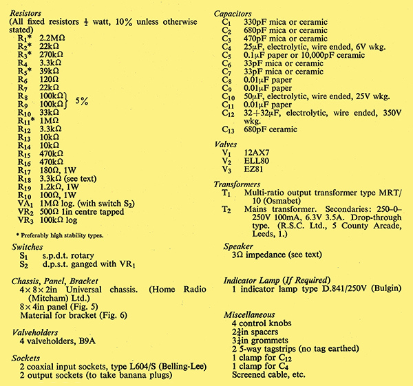
Components list.
The ELL80 is in effect a pair of EL95 output valves in a single envelope. - ed
|