|
Beginners are often puzzled as to what valve they should bay for a particular set. This article, by clearly indicating the purposes for which the various types are designed, will clear away these difficulties.
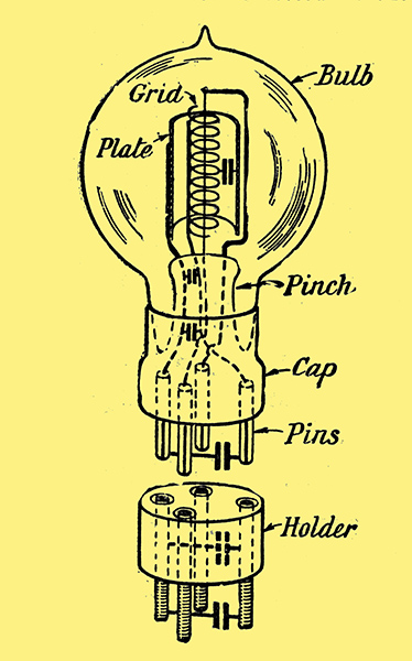
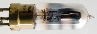
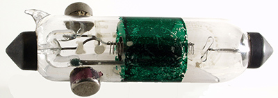
Details of the three electrode valve and its holder.
Little more than a year ago there were only two or three types of receiving valve available for amateur use, and the characteristics of these were so well known that one had small difficulty in coming to a decision when a choice had to be made. To-day the position is entirely different, for there is a positive wealth of valves; we are suffering, in fact, almost from an embarras de richesse. I have not totalled up the number now at the disposal. of the amateur, but at a rough estimate there must be the best part of a hundred of various types and different makes, every one of which has its own special points.
Bright Emitters
The first thing for the amateur to decide is whether he shall use ordinary valves or dull emitters upon his apparatus. If he lives in the country, so that he cannot readily get his accumulators, charged, his choice is to a great extent decided for him by circumstances; he will go for one of the dull emitter types, whose low consumption makes it quite possible to work them from dry cells. But how is the enthusiast affected who has every facility for accumulator charging? In his case has either type any particular advantage over the other? Here are the points in favour of the high temperature valve. To begin with, its initial cost is comparatively low. This means that should one of those little accidents that will happen even in the best regulated wireless sets occur, one does not suffer the same pangs if a bright emitter plays the part of a burnt offering, as one would have done had the sacrifice been a dull emitter. Further, thirty shillings worth is just as easily dropped as twelve shillings and sixpence worth. So far, then, the older type of valve has it. We must also consider the fact that as its filament is designed to carry a comparatively large current ranging from 0.4 Ampere in some types to as much as 1.0 Ampere in others, it is not nearly so much affected by slight overloads as the dull emitter, which may be rendered useless by being run under too heavy a current for quite a short time.
Rheostats
For valves of this kind moderately priced rheostats of standard make are quite suitable; but when we come to the dull emitter, we cannot obtain good results unless we provide something more elaborate, and therefore more expensive. The bright emitter valve is a delicate piece of apparatus in every sense, but the dull emitter is still more so. It is comparatively easy to duplicate valves with filaments designed to work upon, say, 0.4 Ampere at 3.5 Volts. But it is a much more difficult business to reproduce exactly a valve whose filament is very much finer than a human hair. I do not say that dull emitters are uneven, but I do say that at the present time you will find rather greater regularity in a batch of bright emitters than in a similar combination of dull emitters. Unless, however, you go in for careful experimental work, the slight differences that are to be found between individual dull emitters of the same make will hardly be noticeable. Your bright emitters you may treat with a certain amount of disrespect. They will stand what I may describe as 'careful rough handling'. With them you will break all the recognised rules by committing, without doing them much harm, such misdeeds as switching on or off without the use of the rheostat, and using a vastly excessive plate voltage; you may leave them lying about on your bench, you may even drop them (though this is not advised) short distances on to hard surfaces. Yet in spite of this they will give you good service for a very long time. The older type of valve, then, has a very great deal to recommend it, and it is unlikely that for some time to come the experimenter will discard it altogether in favour of its low consumption counterpart.
Dull Emitters
And what is there to say on behalf of the dull emitter? A very great deal, as we shall see. In the first place the high initial cost is offset by increased economy in working and by a longer life should no accidents occur to the filament, which runs only at a dull red heat and is therefore not so rapidly disintegrated. I want to consider dull emitters from the point of view, not of the dweller whose home is far removed from a charging station and who will therefore naturally use dry cells, but of that of the wireless man who has no difficulty at all in having his accumulators attended to when they require it.
Accumulators versus Dry Cells
Let me say at once that anyone who can use an accumulator for heating the filaments of his dull emitters should do so in preference to employing any kind of dry cell. A moments thought will show the reasons why this will give steadier and better working. The dry cell, no matter what its size, is not naturally suitable for delivering a continuous current, even if the amount be small. Directly the cell is placed under load its voltage begins to fall. If the current is small, the decrease in EMF will be slow, but there will nevertheless be a certain decrease. This means that to obtain absolute evenness in working, one, would require to fit to the rheostat a clockwork device on the lines of that which moves the astronomers, telescope. The resistance would thus be decreased progressively, to compensate exactly for the tall in voltage.
Advantages of the Accumulator
With the accumulator we work, so to speak, along a straight line. Once the cell has settled down after being charged, it retains its EMF with no falling off for a long period. We can thus find the best adjustments of our valves, and leave them set with the assurance that we are obtaining the best that they can give. When signal strength begins to decline we know that it is time for the accumulator to visit the charging station.
Disadvantages of Dry Cells
But with the dry cell we are working in a series of ups and downs, which, tiny though they may be, make a good deal of difference. What I mean is this, we adjust our rheostats and get the set working well. At the end of an hour or two reception is not quite so good as it was; therefore we reduce the resistance in the filament circuits a trifle and bring it up again. Actually strength has been falling off almost imperceptibly the whole time, though we did not notice it until the weakening became marked. So much for the filaments; but it must not be forgotten that the same up and down process is occurring in the grid circuits as well. On the high frequency side let us suppose that we are working a one Volt valve from a single dry cell. Across the rheostat in the negative leg of the filament there is a drop of 0.5 Volt; hence, when the battery is up to its full voltage, the greatest positive potential that we can apply to the grid is one Volt. With the decline in voltage the grid potential falls off; hence the valve tends to become less and less balanced whilst it is worked continuously. With the accumulator none of these things occur and much steadier working is obtained.
Questions of Cost
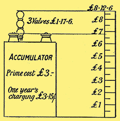
Fig. 1. Diagram showing price and working cost of three bright emitter valves.
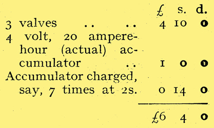
Now let us consider the annual budgets of two wireless men using similar three-valve sets. The first purchases a trio of ordinary valves with a voltage consumption of 0.5 ampere.
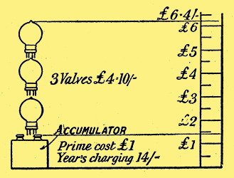
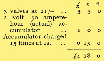
Fig. 2. Diagram to the same scale as Fig. 1, showing the cost when using 3 0.06A valves.
The second a set of dull emitters using 0.06 ampere. Each works his set on an average of two hours a day, or, say, 700 hours during the year. Here are the first mans accounts.
The seciond mans' accounts are as follows.
Dull Emitter Economy
The dull emitter, therefore, represents a considerable saving at the end of twelve months working. In addition, it must be remembered that after 700 hours work 'bright emitter' valves will be approaching the end of their career, even if some of them have not already succumbed, though the dull emitters would, as a rule, be good for at least as long again. Even if we allow each of our users to break or burn out two valves of this particular type during the period the balance will still be slightly in favour of the dull emitter #9 4s, as against #9 17s 6d.
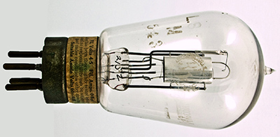
The ARDE
The Ediswan ARDE.
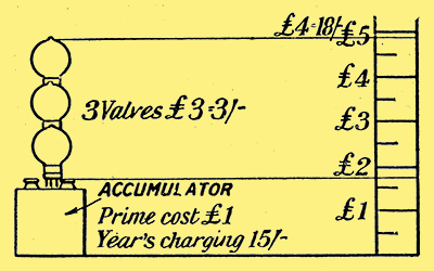
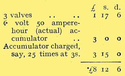
Fig. 3. Illustrating the costs with 3 ARDE valves. With DER valves charging would approximate 18/-.
If a rather more robust dull emitter such as the Ediswan ARDE were chosen for the test, the figures would be as under. Here the valve consumes 0.3 Ampere with a potential of 1.5 Volts.
Here the user may break and replace all three valves during the year and still be on the right side as compared with the bright emitter man. Dull emitters, then, certainly make for economy, and if they can be worked off accumulators they will give results that will bear comparison with those produced by bright emitters of the same class.
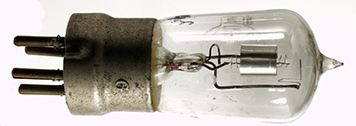
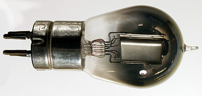
The DEV and DEQ
The Marconi DEQ.
When I say of the same class I mean that with two exceptions all dull emitters are general purpose valves. It is therefore not fair to compare their performances with those of bright emitters especially designed for particular purposes. The two exceptions are the DEV, which is the low temperature counterpart of the V24, and the DEQ, which represents the Q valve in (dull emitter form. These are both very expensive valves, their price being in the neighbourhood of 35s. apiece, and I am not sure that they are easy to obtain at the present time.
Three Purposes of the Valve
The general purpose valve is, of course, a compromise. It is not always realised that on the multi-valve set the valves are called upon to perform three entirely different duties.
High-frequency
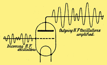
Fig. 4. The high-frequency amplifier's duty.
The valves on the high frequency side receive from the aerial or from the valves preceding them oscillations at radio frequency which, when we get down to such a short wavelength as 100 metres, occur 3,000,000 times a second. Their business (Fig. 4) is to amplify these oscillations and pass them on so that the form of the waves is absolutely unaltered, save that their amplitude is increased. The greater the frequency the more will the effects of any small capacities, be felt. Hence it is desirable that these valves should be so designed that capacity between electrodes and between the points of the seating should be reduced to the lowest possible degree. Further, in order to prevent distortion from occurring, we require a valve in which the flow of grid current will be very small when the grid is in the neighbourhood of zero potential. On the high frequency side a high impedance in the valve is an advantage.
The Rectifier or Detector
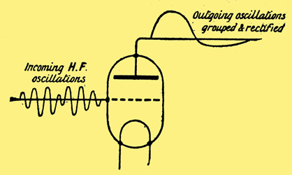
The rectifier's task.
The rectifying valve presents a different problem, Its function is to receive oscillations, either direct from the aerial or in an amplified form from the high frequency circuits, to reduce them to audio frequency and to pass on waves in which one half of each cycle has been as nearly as possible eliminated; the nearer the approach to the complete elimination of half cycles the more efficient will rectification be. Rectification may be done in two quite different ways; we may make use of the lower bend in the grid-volts plate-current curve or we may use the bend in the grid-volts grid-current characteristic. Certain special rectifiers such as the Q are intended for plate rectification and are therefore designed to have a very marked lower bend in the grid-volts plate-current curve. It may safely be said, however, that ninety-nine per cent of the receiving sets now in use employ grid rectification which is accomplished by means of grid-leak and condenser. It is desirable that the rectifying valve, whichever form of rectification is used, should have low. capacity since it has to deal with oscillations at high frequency. It should also have a fairly low impedance to match that of the telephones or of the primary of the transformer which follows it.
Note Magnifier or Low Frequency Amplifier
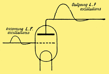
Fig. 6. What the note magnifier does.
Note magnifying valves have a very much simpler task than either of the others (Fig. 6); the first place they have to deal with oscillations at audio-frequency whilst capacity effects are not nearly so marked, and, secondly, oscillations which. come to them have already been rectified. Low capacity, then, has not nearly the same importance as with valves of the other two classes. The most important requirement in a low-frequency amplifying valve is that it shall possess a characteristic curve with a long straight portion. If the straight part is short the operating point may pass round the bend at top or bottom, and distortion will result when strong signals are being received.
Grid Potential
It is desirable that the potential of the grid be kept considerably negative; hence the flow of grid current is automatically kept clown. What is essential is that the straight portion of the curve should be very long,for if it is not the peaks of the waves will be cut off by their raising the grid potential to the point at which the upper bend in the curve occurs, as has just been explained. In the note magnifying valve a fairly low impedance is desirable for the same reasons as those which affect the rectifier.
General Purpose Valves
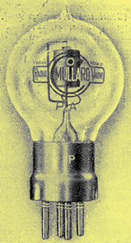
Mullard ORA.
A general purpose valve, such as the Mullard ORA, the M-OV R and R5 the Ediswan AR and the Xtraudion, is designed to function in any part of the set. Hence its curves, its impedance, and its capacity must all be averaged. That is to say, it will give good performances anywhere, but it is hardly fair to compare it with special purpose valves. To take an analogy of life a well-bred horse of sturdy build might be used for hacking, for hunting, between the shafts of a trap, or in the plough; it might even win a point-to-point race. It would do all these things quite well, but they would be done rather better by hackney, the cob, the hunter, the Clydesdale and the thoroughbred, each of which a horse bred for a special purpose.
With the two exceptions mentioned, then, all dull emitters are general purpose valves. Valve manufacture and design have been brought to such perfection nowadays that the general purpose valve gives amazingly good performances in any part of the set.
Above is a list of the dull emitters now available, with their particulars and some notes on their qualities. The valves listed are: DEV, DEQ, ARDE, DER, LF ORA (a, b & c), Wecovalve, Wuncell, DE3, AR06, B5, DF ORA - ORA, MO R, R5, AR, Xtraudion & BTH R.
British-manufactured valves the Best
The quality of the British general purpose valve is extremely good; in fact in no country in the world are amateurs so well, provided for by valve-makers as in this. One can, therefore, purchase any type of valve of this class with entire confidence that it will be all that is expected of it. The purchaser should be guided to some extent by the size of his accumulator and the facilities for charging which are at his command. If for example, he possesses a large low-tension battery and is the fortunate owner of the Tungar or some other equally good home-charging apparatus the amount of current consumed does not matter to him. On the other hand, the man whose accumulator is of small ampere-hour capacity will be well advised to go for valves whose filaments have a comparatively low rating; for if batteries are never put under too heavy a load their life is very greatly prolonged.
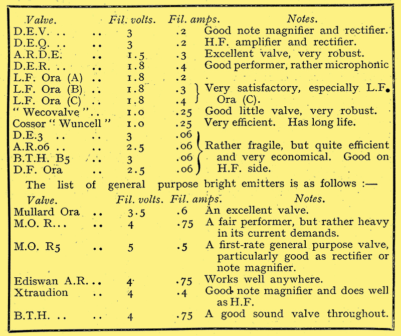
Special Purpose Valves
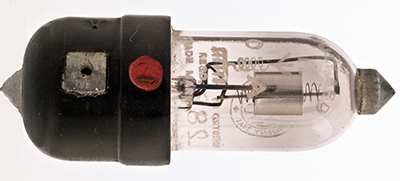
Of the special purpose valves; there are many interesting and extremely useful kinds. The first are those which are so designed as to eliminate as far as possible the capacity between electrodes and between the points of attachment to the mounting. The points at which capacity occurs are seen in the figure. Perhaps the best known of these is the famous V24, a valve of the test-tube type, in which the filament is suspended between supports sealed into the glass at either end, whilst the grid and plate contacts are at either side of the tube.
V24 and Q Valve
Marconi V24 and Q
V24 was designed particularly as a high-frequency amplifier, in which position there are few valves to equal it for short wave work. The rectifier of the same class is the Q valve, and its improved form It is of the same shape and size, the main constructional differences being in its grid and plate, which are especially designed for the work which it has to do. This valve is intended to function as a plate rectifier, working upon the lower bend of the characteristic; it therefore needs neither grid-leak nor condenser. It also makes a very efficient high-frequency amplifier, though owing to its amazingly high impedance, which is of the order of 250,000 Ohms, it will not work well as a note magnifier except on sets with specially designed inter-valve transformers. Both V24 and Q require 0.75 ampere at 5.0 volts. They are rather expensive valves, but if carefully handled their life is along one. These valves are especially handy in making up sets .Where space is limited, since owing to their small size they occupy but little room.
Special Dull Emitters
DEV and DEQ are the dull emitter equivalents of the preceding. Using the e valves myself, though no direct reaction is used, all British broadcasting stations, as well as those on the western side of the Continent, come in at good loud-speaker strength, and American broadcasting is often received on the loud-speaker. These valves are rated at 0.2 Ampere at 3 Volts. My experience is that the current required is usually rather less than the amount stated. The present quartet show an ammeter reading of 0.7. They are worked off a 4 Volt 50-ampere hour (actual) accumulator, which, in spite of the fact that the set is in pretty constant use, makes very rare visits to the charging station. The valves in this case are two DEQ.s on the high-frequency side and two DEVs as rectifier anode note magnifier. The plate voltage used for the HF valves is 40, and for the others between 60 and 70. The high-tension current consumption is 6 milliamperes, which is well within the powers of an ordinary high-tension battery.
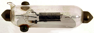
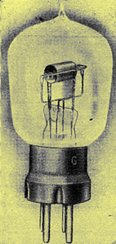
Mullard Valves
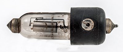
The Mullard ORA B.
Another good series of anti-capacity valves is that made by the Mullard Company. The first of these is the ORA B, which is simply the well-known ORA valve made up with a special mounting. As will be seen, the filament contacts are at the point of the cap and at the end of the tube, whilst grid and plate connections are placed at either side of the cap.
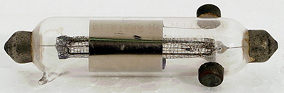
Mullard S3.
Others of the series which are similar in design, though smaller in size, are the S3 and the S7. The former is specially designed for low anode voltages, working quite well with as little as 15 Volts on the plate. I have actually obtained quite good signals whilst using a single flash-lamp battery for the anode supply. S7 is a first-rate rectifier.
Cossor Valves
The Cossor P1 and P2.
Two other good special purpose valves are the Cossor P1 and P2, the former being a very good rectifier and note magnifier, whilst the latter is a high-frequency amplifier of particular merit. In this connection I should say that the Cossor Company are now making a special form of their Wuncell valve, the P4, for high-frequency work. I have not had the opportunity of testing this valve, but I hear good reports of it. This is, of course, a true dull emitter working at 1.0 Volt and consuming about 0.2 ampere.
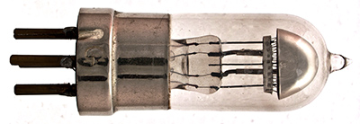
Power Valves
The Mullard PA Valve. The series consisted of the PA.1, PA.2 and PA.3
The valves known as power amplifiers form a class by themselves. They are intended for loud- speaker use with very high anode voltages where a large volume of sound is required. For this reason they have been designed to give a very long straight portion of the grid-volts plate-current characteristics. A very efficient member of this class is the Mullard PA (PA.3) which consumes 0.85 Ampere on the filament with a working EMF of, from 3.6 to 4.0 Volts. The anode voltage is usually from 150 to 200; with the latter amount the emission at zero grid volts is 22.5 milli-amperes.
The Marconi LS5.
The MO Valve Company turns out two very good types, the bright emitter LS2 requiring 6 Volts and consuming rather more than an ampere of current, and the dull emitter LS5 which consumes only 0.4 ampere.
The BTH B4.
The BTH R valve B4, whose filament current is 0.25 ampere at 6 Volts, works well with from 40 to 100 Volts on the anode. It is a very satisfactory power amplifier, which will meet all the requirements of those who require a large output from the loud-speaker.
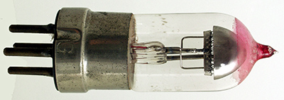
Special Rectifiers
The Marconi R4C.
Very few special rectifiers are available for the amateur, and as a matter of fact there is little to be gained from using one in sets which have one or more stages of high-frequency amplification. One type, however, may be mentioned as being particularly good, and this is the MO R4C, whose filament current consumption is 0.65 ampere at 3.8 Volts. This valve was, I believe, designed for use in the Navy. It is a splendid performer, and will stand any amount of work.
Dutch Valves
For the single valve man there is nothing to beat one of the soft Dutch valves which are now obtainable at low prices from advertisers. The type recommended has a vertical grid and plate with a U-shaped filament. It is a rather squat cylindrical valve with a standard 4-pin mounting. If one can get hold of one of these valves with exactly the right degree of softness wonderful results can be obtained with a single valve set. Those who contemplate purchasing one should endeavour to see it tested in the shop and to select one which blue-glows with between about 35 and 50 Volts on the anode. It should be worked with a plate voltage in the neighbourhood of 25 with the filament fairly bright, though not bright enough to crackle. These valves are very stable; in fact, it is difficult to make them oscillate if one tries to do so. They are therefore ideal for use in single valve sets employed for broadcast reception. Owing to their rather soft nature the emission from the filament is high, since ionisation by collision occurs. Rectification is extraordinarily good, and with even a single valve a broadcast station 30 miles away can be brought in quite as strongly as is comfortable with the telephones. I have actually worked a loud~ speaker from a single valve set, bringing in 2LO, whose distance from my station is that mentioned, with sufficient volume to make the music audible to everyone in a room 15 ft. square.
Soft Valves
It would, I think, be a good thing if British makers were to turn their attention to the soft rectifying valve, for I am sure that it would have a very large sale amongst amateurs. Our American friends have plenty. At the present time it is the single valve sets which cause most of the trouble by oscillating during the reception of broadcasting. The hard valve oscillates as a rule quite readily, and when it is worked at its most sensitive point the slightest adjustment of the controls may produce re-radiation from the aerial. The soft valve, on the other hand, is much more stable when worked at its sensitive point, and as its tendency to oscillate is very small it is not nearly so likely to be guilty of causing interference. If, therefore, a soft valve of well-known make were available for general use I believe that interference, which is at present a serious problem, would be very greatly reduced.
Conclusion
In this article an attempt has been made to give a brief survey of the various kinds of valves which are at the disposal of the wireless man. I have. used every one of those mentioned, with the exception of the Cossor Wuncell, and my experience has been that taking our valves as a whole British amateurs have nothing to complain of the way in which makers cater for their needs. There is one small improvement in the boxing of valves which might very well be introduced. In buying a valve of well-known make at the present time one knows that the valve itself is a good one, but there is no guarantee that it has not been used for demonstration purposes, and perhaps seriously overloaded. There is no reason why the valves should not be put in sealed boxes with the tips of their pins only protruding and with a small hole cut in the side of the box. The purchaser could then see the valve's filament tested, and he would buy it with the knowledge that he was obtaining a brand new article which had not already seen a good deal of work.
|