|
This article is a continuation from the previous week - a copy that we have not yet found. - ed
With valves of the hexode type, fluctuating mains voltage does not cause any material frequency drift. The size of the virtual cathode is but slightly affected by changes in the first accelerator grid voltage. Although an increase in the voltage of the accelerator grid does not extract more electrons from the cathode space charge, the velocity of the electrons also increases and at higher speeds, the density of the space charge diminishes. These effects will balance each other fairly accurately, and the change in the oscillator anode voltage has but a slight effect on the impedance of the triode, and consequently on the phase lag of the anode current. With triode-hexode types (and, of course, triode-heptodes) a 10% fluctuation in mains voltage causes about 2 kHz frequency drift at a frequency of 17 MHz.
As against this in the older octodes VO4 and EK2, fluctuations of supply voltage cause fluctuations in the transit time of the electrons reaching the oscillator anode and produce considerable frequency drift.
The efforts to eliminate the observed detects in the older octodes led to the development of type EK3. This makes use of electron-optical principles and represents a radical departure from previous frequency-changer design.
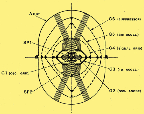
Fig. 1. The arrangement of the electrodes of a modern octode is shown in this diagram. The bar structure of the oscillator grid divides the electrons into four beams.
Fig. 1 shows how the four side rods of the first grid G1 divide the electron stream into four beams. Two opposite beams impinge upon the oscillator anodes G2, which are constructed to have angle-iron profile. Thus, the transit time of the electrons is as short as in a normal triode the first accelerator electrode G3 is made of solid sheet metal, electrostatically screening the oscillator anode, and partly screening the first control grid as well. The pairs of side rods of the first grid and the aperture of the first accelerator electrode are so designed that the electrons flying towards the second control, grid G4 are accelerated by it without, however, impinging upon it. Thus, a virtual cathode is formed between the first accelerator G3 and the second control grid G4 and, consequently, a part of the electron stream returns towards the accelerator. This being made of solid sheet metal, absorbs all returning electrons and prevents their return into the neighbourhood of the first space charge. Those edges of the first accelerator aperture which face the second control grid are so formed that their electrostatic suction effect attracts even those electrons which would otherwise fly back through the aperture of the first accelerator. It is clear, therefore, that by this means, all the aforementioned defects are simultaneously eliminated.
The principal operating characteristics of the EK3 are a conversion conductance of 0.65 mA/V, with an oscillator peak voltage of 10 Volts ; the working slope of the triode is 4.5 mA /V.
From the above it will be seen that the EK3 is a worthy rival of the triode-hexode type of valve, since the gravest defect of octode valves, namely, frequency drift, is entirely eliminated in it. In octode types, however, space-charge coupling is still a drawback which even if neutralised can still cause some defects. On the other hand, the disadvantages of the triode-hexodes are low input impedance and variations in grid capacity.
We will now only add the following observations on space charge and its neutralisation: the neutralisation of space charge coupling by means of capacity coupling only is never a complete success because the finite transit time of the electrons retards the grid current due to space charge. In order to adjust the phase error, therefore, we must connect an additional resistance in series with the coupling capacity. The time constant of this resistance-capacity system is approximately equal to the transit time of the electrons, which in type EK3 is 2 x 10⁻⁹ sec. Hence, the coupling elements introduced between the first and second control grids have values of 1,600 Ohms and 1.3pF. However, this manner of neutralisation is only perfect at a single predetermined oscillator voltage. This is due to the fact that the voltage induced by space charge coupling becomes practically constant above a certain oscillator voltage while the capacitively transferred voltage compensating it will increase continuously with the oscillator voltage. The above values give a good practical balance to an oscillator voltage of 12 Volts eff. (The dissimilarity of this effect to that of the limitation of conversion conductance should be noted).
The Oscillator Circuit
As these coupling elements are built into the EK3, it is not advisable to connect the oscillator tuned circuit to the first control grid for two reasons:-
The resistance-capacity combination, while stopping the effect of the oscillator grid upon the signal grid actually assists the transference of signal-frequency voltage from the second control grid to the first control grid. If the oscillator tuned circuit is connected to the first control grid, a signal voltage will consequently appear on it. It must be remembered that at short waves, where the percentage difference between the input frequency and the oscillator frequency is very small, the oscillator circuit will have quite a high impedance to the signal frequency. This unintended signal voltage on the first grid will be additively mixed with the oscillator frequency voltage, thus creating an intermediate frequency component in the anode current, which will either increase or decrease the normal multiplicatively produced conversion gain of the valve. This in itself would not be a serious defect except that the valves are not quite uniform with reference to this unintended function, there being a likelihood that in a batch of EK3 valves used in one and the same receiving set a difference in sensitivity of 1 to 4 may occur.
If a tuned grid oscillator circuit is used trouble also arises due to AVC, as the neutralising balance will not be at an optimum through changes in signal grid bias. Thus, the signal voltage on the second control grid will influence the first grid potential and thus the frequency of the oscillator. However, if the tuned circuit is connected to the oscillator anode, both these defects are reduced to a negligible minimum.
Hexode type Valves
In hexodes, space charge coupling also occurs, but of a somewhat different type, the injector grid repelling more or less electrons towards the first accelerator in step with the oscillator frequency. Some of these electrons pass through the first accelerator and increase the cathode space charge, producing an oscillator-frequency voltage upon the first grid by influence. It is clear, however, that the magnitude of this coupling is practically negligible, its value being of the order of 0.01 pF. in comparison with 0.1 pF. for the electrostatic coupling between the first and third grid of the hexode.
The returning electron current in hexode valves causes other serious disorders which are by no means negligible. The space charge increment near the first grid increases the input capacity and this varies in inverse proportion to the signal grid bias, and will disappear completely above a certain signal grid bias value. The change in input capacity due to the action of AVC in triode-hexodes is about 2-2.5 pF. Distortion occurs through the RF input circuit becoming detuned, which can be in unfavourable cases as much as 3 to 5 per cent., a perceptible amount in high- fidelity receivers. Detuning of the input circuit is, of course, not as detrimental as detuning the oscillator circuit, since it mainly has the effect of altering the impedance offered to the signal frequency, whereas the oscillator circuit will affect all intermediate frequency circuits.
Severe changes in capacity will increase the input damping of the signal grid as well. This effect has been fully expounded in other earlier publications where it was shown that the dephasing of the capacitive current in consequence of the electron transit time will produce a resistive current component. This damping causes a perceptible decrease in gain at wavelengths as long as 12 metres, so that on ultra-short wavelengths it is advisable to connect the signal grid to a tapping point on the input tuned circuit.
The capacity variation and damping of the signal grid, the EK3, is much less than that with the triode-hexodes, and is even better in this respect than RF amplifier pentodes.
This is due to the fact that the virtual cathode in the EK3 is mainly a function of the cathode current, so that the change in capacity under the influence of AVC amounts to only a few tenths of one pF the input impedance at 15 metres being approximately 100,000 Ohms.
From the foregoing it is clear that very vast improvements have taken place in mixer valves, and their use in receiving sets is now almost as simple as that of ordinary amplifier valves. They do not as yet function faultlessly on the ultra-short wave-band, but further improvements no doubt will bring the solution of this problem also.
|