|
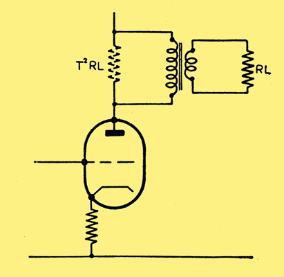
Fig. 1.
You have just designed a new receiver, and are quite certain that the frequency response is as good as it can be under the circumstances. Bags of negative feedback, valve line-up carefully considered, low distortion detector, voltages just right, and so on.
The components are all carefully specified. Valve types, resistor values and ratings, and whether carbon or wire-wound. Capacitors, too, are accurately specified as mica, paper, or electrolytic; the capacitances are clearly stated and the voltage ratings.
But the output transformer - this Cinderella of radio components - what sort of treatment does it receive? It is specified, of course, but often as not in a very vague manner. For example: Output transformer, ratio 25 : 1, to deliver 8 Watts. Just that and no-more. No mention of its primary inductance, which is one of its most important characteristics. It is this which makes all the difference between a good transformer and a bad one.
A transformer with inadequate primary inductance - and there are plenty of them to be had in the shops - will make the beautiful response curve of your amplifier look like something brought in by the cat. It will accept a faithful reproduction of your favourite record from the output valve, and deliver a horribly mangled and mutilated version to the speaker.
Why, then, should there be plenty of inductance in the primary? Well, take a look at Fig. 1. Here we have an output valve feeding a transformer of turns ratio T, with a load resistor RL, the speech coil of the speaker, connected to its secondary. As we know, this arrangement gives an effective load resistance at the valve anode - that is to say across the primary - equal to the square of the turns ratio T multiplied by RL, in other words T2RL. This effective resistance is shown in broken lines, and its value should be equal to the recommended load for the valve.
A numerical example will make this quite clear. Suppose the recommended load for the valve is 4500 Ohms, and we wish to use a speaker having a 3 Ohms speech coil. In this case the required transformer ratio must be 38.7 : 1 since 38.72 x 3 = 4500. In practice, of course, the ratio need not be so exact as this.
But, as we can see from the diagram, the reactance of the primary is in parallel with the reflected load resistance. If the primary inductance is, say 3 Henries, its reactance at 50 Hz will be approximately 940 Ohms. This in parallel with the reflected load of 4500 Ohms gives an effective load of only 780 Ohms! The response will thus fall considerably at the low frequencies. As the frequency is increased, so also will the primary reactance increase, and at 5 kHz will be approximately 90,000 Ohms; the parallel effect of this on the load resistance will be negligible. Thus, in order to avoid a poor low frequency response, we must make the primary inductance high, and so obtain a high parallel reactance.
There is another reason for having a high primary inductance, especially where the amplifier has a low output impedance such as is obtained with triodes or pentodes with negative feedback. An output valve with its correct load is rated to give a certain maximum undistorted current output. If, however, the load is effectively reduced at low frequencies, due to the parallel effect of the primary reactance, then the signal current will increase beyond the safe maximum, and will result in a particularly objectionable form of distortion.
This amplitude distortion, as it is called, becomes negligible only when the primary reactance is some three or four times as great as the load resistance, in this case about 18,000 Ohms. At 50 Hz this would call for a primary inductance of 40 to 50 Henries!
In single valve output stages it is difficult to obtain very high inductances due to the passage of heavy DC currents through the valve and windings of the transformer. The economical maximum for components in such circuits is in the region of 6 to 7 Henries and will usually be somewhat less than this. Nevertheless, the principle remains. If you want reasonable quality use as high an inductance as possible. Eschew cheap and nasty components. Reputable manufacturers will always be prepared to supply you with all the relevant data concerning their products.
With push-pull circuits, of course, it is relatively easy to obtain high inductances of more than 50 Henries, though measurements on some of the alleged push-pull transformers at present on the market would lead one to believe otherwise.
In conclusion, then, when you buy an output transformer always ask the value of the primary inductance. It is just as important as the turns ratio, and if a maker cannot or will not give a figure, you can be sure that it is not worth having.
|