|
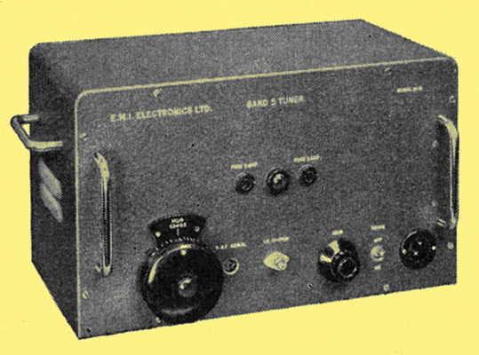
The Band V convertor assembled as a self-contained, screened unit, including power supply.
Experiments are being conducted to ascertain the possibilities of this band, using different television systems and types of receiver. For this purpose the BBC are transmitting signals from their station at Crystal Palace and the reception at various places is being assessed. Some of the receivers, however, are of a type unsuitable for ordinary domestic use at present.
One of the principal problems facing the designer of a television receiver for use at UHF is the noise factor. In the USA, where this band is already in use for television broadcasting, it is common practice to use no amplification at UHF, the signal being fed directly into a crystal diode mixer. The local oscillations are often derived from a harmonic of the existing VHF (Band III) oscillator. This yields a noise factor of some 18 to 20dB at 650 MHz owing to the conversion loss in the crystal and the presence of noise sidebands with the oscillator harmonics. It is, however, neat and cheap since the entire unit can be built on to one position of an orthodox television turret tuner.
The use of Lecher lines or resonant cavities for the UHF circuits, and a separate UHF oscillator, would give an improvement in the noise factor of 16 to 18dB. Experimental models have been described which are much better than this, down to 10 to 11dB, but these are not in commercial use at present.
The addition of an RF amplifier stage will permit a worth-while improvement in the noise factor, but only a few valves really suitable for this application are available. The older disc-seal triodes achieve their performance by running with high anode currents, and it is necessary to use them in conjunction with large masses of metal to act as a heat sink for the anode seal. This form of construction is admirably suited to ultra low-loss co-axial circuits but would be prohibitively expensive for domestic use.(See DET23 ed.)
Recently introduced valves, however, will give satisfactory performances as UHF amplifiers with only modest anode currents. One such is the M-OV. Type A2521 which has an ordinary B9A base and the electrode assembly mounted horizontally and directly on the header pins. The claimed performance for this valve as an RF amplifier at 650 MHz is a power gain of 13.5dB with a 13 MHz bandwidth and a noise factor for the stage alone of 10dB.
A number of convertors have been manufactured and supplied for experimental Band V reception by EMI Electronics to the order of BREMA. These use an A2521 valve as an RF amplifier, another as the local oscillator and a radar-type crystal diode, CV2155, as the mixer. This RF section is followed by a cascode double-triode first IF amplifier and two further pentode IF amplifiers as shown in the circuit diagram. The output is intended to be fed to a television monitor, or to a receiver having provision on the channel-selector switch for accepting a signal at the standard television IF.
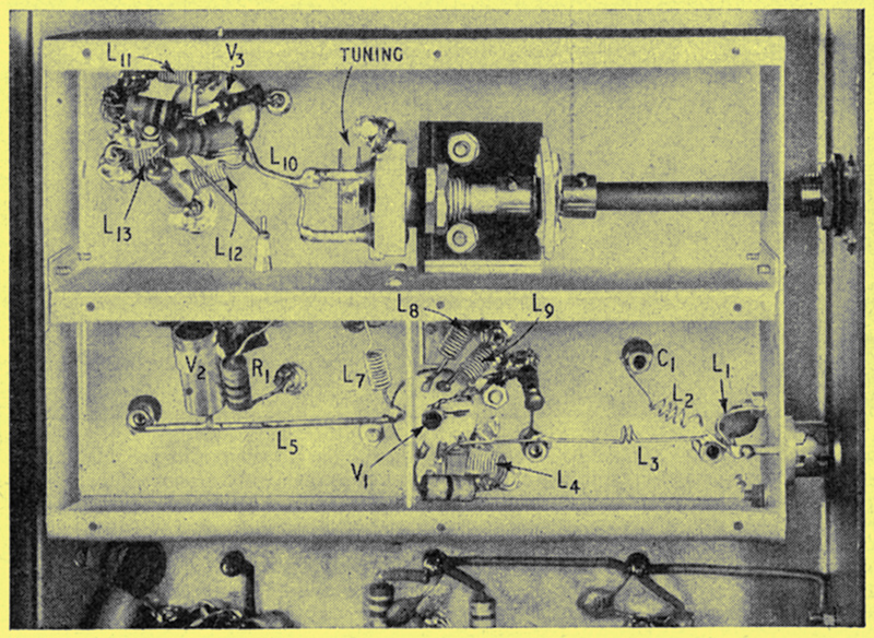
RF, mixer and oscillator section of the convertor; it comprises that part of the circuit enclosed by broken lines.
Since the valves are conventional plug-in types, it was decided to attempt to use ordinary television receiver-type components throughout. Series resonant circuits tuned with ceramic tubular preset capacitors have been found quite satisfactory, although the inductor reduces to a straight piece of 16 s.w.g. wire in some places. Small chokes of 0.1 in diameter and self supporting, wound with a few turns of silk-covered wire are used where necessary and have been found to introduce negligible loss. In fact there are very few unconventional parts of the circuit. As can be seen in the illustration of the UHF portion of the convertor, the oscillator anode inductor consists of two wires in parallel, the spacing between them being adjusted on test to bring the oscillator to the correct frequency with the variable capacitor at mid travel, thus obviating the necessity for a trimming capacitor, which would reduce the oscillation amplitude and restrict the frequency range available on the main tuning capacitor. Local oscillations for injection into the mixer circuit are taken from the live heater of the oscillator valve, and thence to earth through a 270 Ω resistor (R1) placed close to the crystal. Adjustment of the relative position of V2 and R1 permits the optimum crystal current to be achieved, while the resistance limits the heater current flowing.
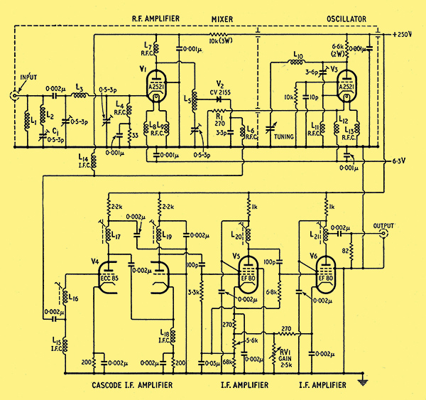
Theoretical circuit diagram of the Band V television convertor described in the text. The tuning capacitor is a modified air-space trimmer with plates removed to leave one fixed and one moving. All resistors 0.5W unless otherwise stated. Valves: A2521, ECC85 & EF80.
This arrangement has been found to give constant injection over the tuning range with negligible pulling or loading effects on the oscillator. The band-width of the RF circuits is set by adjustment of the crystal tap position on L5. The rather large capacitance of the aerial input socket is roughly tuned out by an inductor (L1), connected to the chassis and consisting of about one inch of wire; it gives the appearance of a short circuit on the input. A series resonant circuit (L2C1) at the image frequency (727 MHz) is also added across the input circuit. This consists of a pi network adjusted to give optimum aerial coupling for minimum noise factor. The coupling required differs considerably from that giving maximum power gain. Although not of primary importance in this application, it has been found that the oscillator drift over long periods of use is less than 500kHz.
The performance specification achieved by this convertor is:--
Frequency - 654.25MHz, tunable ±5MHz. Gain - 40dB. Input and output impedance - 75 Ohms. RF Bandwidth - ±6.5MHz to -3dB points. IF Bandwidth - 33 to 40 MHz, flat ±1dB. Noise Factor - 10.5 to 11dB measured in 3 MHz bandwidth. Spurious responses at least 30dB down.
|