|
The story of how the valves were designed for high-power transmitting stations intended for the transatlantic services. Many difficult problems had to be solved, and all sorts of difficulties overcome, as described in this article.
When it was known that frequencies of the order of thirty thousand kilocycles would play a part in transatlantic communication, investigations were immediately undertaken in America to determine the types of valves most suited for transmission systems operating at such high frequencies.
It was found that the valves which had met the requirements of the long-wave service, using a carrier frequency of the order of 75 kilocycles, were not suitable for short-wave systems.
Such valves could not be operated in parallel at the high frequencies; and even when used singly they had an extremely short life unless operated at considerably reduced plate voltages and output powers.
There are several reasons why valves that were structurally satisfactory for the low frequency range were inadequate for the high-frequency range.
In the first place, at high frequencies the inter-electrode capacity of the valve becomes very important as regards the circuit.
Why Earlier Types Fail
The 'charging' or displacement currents which flow through every dielectric in an alternating electric field increase with the frequency of the alternations. These displacement currents heat the various dielectrics (whose power factors are not zero) used in and around the valve, thereby causing its ultimate failure.
A high vacuum is the only perfect dielectric, for heat is not developed in it through dielectric losses.
It can fail only when leaks or a slow evolution of gas from the parts of the valve change both its status as at vacuum and its insulating properties.
The air separating the connections on the outside of the valve will be only about one-tenth as effective an insulator when the valve is oscillating at 30 MHz as compared with the non-oscillating condition, when the same plate potential is applied to the terminals.
Another reason for the failure of earlier types of valves when used in short-wave circuits is to be found in the 'skin effect'.
A high-frequency current passing through a conductor is forced to travel through a very thin layer at the outside of the conductor. The effective size of the conductor is thus reduced, its resistance correspondingly increased, and overheating engendered.
The New Valves
In view of such facts as these, new valves had to he developed and old types modified to work with the new circuits.
Mr H J Kelly suggested several years ago that water-cooled power - amplifiers for short waves should be made double-ended; with the filament structure and leads supported on glass at one end, a water-cooled anode in the middle, and an oversize grid lead supporting the grid structure from the glass at the other end.
In this way a maximum of insulating glass and air separate the leads to the electrodes, and the leads can be made large in 'skin' area.
Preliminary models of water-cooled tubes embodying these features were made in the Bell Telephone Laboratories, and these models were supplied for transmission development work at Deal Beach.
While this work was in progress the final commercial design of water-cooled valves of this type was developed. These valves were standardised and made available for the new transoceanic short-wave service.
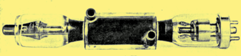
Fig. 1. This water-cooled valve has an output rating of 10 kilowatts. It was specially designed for short-wave working.
One of these valves is shown in Fig. 1, and its grid structure in Fig. 2. It is the Western Electric 240-A valve, with an output rating of 10 kilowatts when working on the high-frequency band.
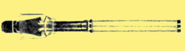
Fig. 2. This is the grid structure of the valve shown in the photo above.
Push-Pull Oscillator
This valve was designed to meet short wave circuit requirements, and then adopted after experimental valves had weathered a long series of severe tests. The circuit used for these tests consisted of a shielded push-pull oscillator.
A heavy straight lead, tapped in the centre with a grid leak, connects the grid terminals of two 240-A valves under test, which are mounted vertically on Pyrex insulators.
The anodes are connected by means of a water-cooled coil, about eight inches in diameter, consisting, of three turns of copper tubing. The capacities of the valves between grid and plate complete the oscillating circuit.
The load is applied by shunting a small section of the inductance coil with hollow water-cooled carbon rods. The temperature rise and the volume of the cooling water supplied to the rods give a measure of the total power output. By means of these tests the power limits of the valve are determined.
Water Mains Affected
Minute as the capacities are between the test circuit and other unrelated circuits in adjacent rooms, the frequency of the testing currents is so high that considerable amounts of power can be transferred across the intervening space.
In spite of radio-frequency chokes in the high-voltage lines of the test set, and the shielding afforded by enclosing the whole circuit in a large aluminium case, high-frequency energy passes by displacement currents through the holes in the shielding, for electric and water supply mains to upset galvanometer readings, reverse manometer micro-ammeters and burn out thermocouples in adjoining laboratories. The tests are, therefore, conducted out of hours.
Another interesting point in the development of valves of this type is the method of evacuation. The 240-A valve is supported on insulators at the middle, and has special ovens fitted over both glass ends.
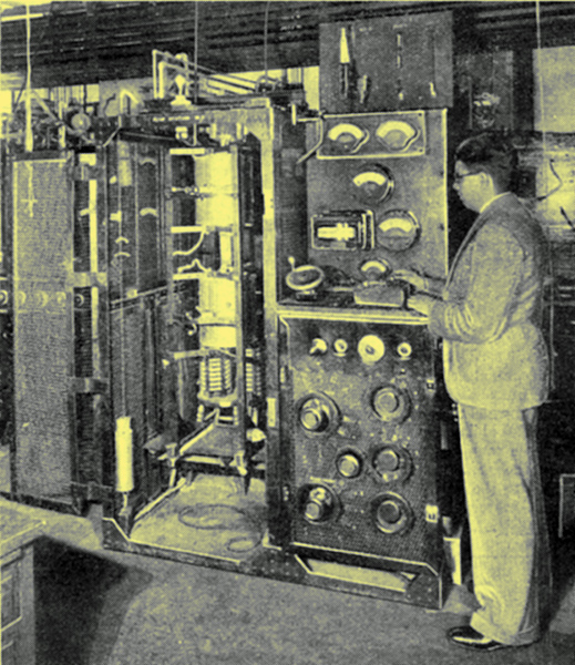
This is the intricate pumping apparatus used for exhausting the short-wave water-cooled valves. Special ovens are fitted over the glass ends, the centre of the valve being held by insulators.
The grid, filament, anode and glass parts 1 are 'outgassed' simultaneously by heating each of these parts to the highest temperature which it will stand and still keep its form.
Quick Outgassing
The evacuation process consequently becomes a relatively short one, as compared with that for other water-cooled valves whose various parts must be 'outgassed' separately. The water jacket becomes an essential part of the valve after it has been pumped.
In order that these valves may be operated successfully in parallel, without singing, their characteristics, and thus their construction, must be as nearly alike as possible.
Fig. 4, a picture of the 241-A valve, shows how the 212-D 250 Watt valve had to be redesigned as a double-ended valve to make it suitable as an amplifier in the earlier stages of short-wave radio-telephone development.
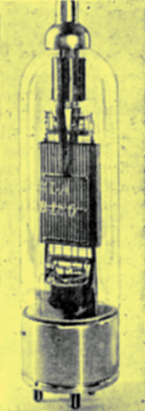
Fig. 4. A 250 Watt double-ended valve.
|