|
Some years ago, out of curiosity I purchased a Chinese hybrid valve/MOSFet headphone amplifier from Bravo Audio. The advert played on the presence of the valve but I could not see how the valve was doing that much. In fact the device was basically a MOSFet amplifier with the ECC82 valve present almost just for show. Follow the ECC82 link for images and description.
This typology would give a false impression to someone new to the world of valves and I started thinking how a real hybrid headphone amplifier should be constructed.
The experimental ECC83 plus ECC82 amplifier from 1964 looked a promising start point. I then discovered the FireFly amplifier designed for guitar practice that also used the ECC82 double triode as a push-pull output stage. The popularity of the FireFly design has encouraged transformer makers to produce the small transformer required.
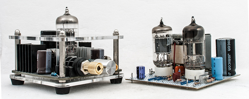
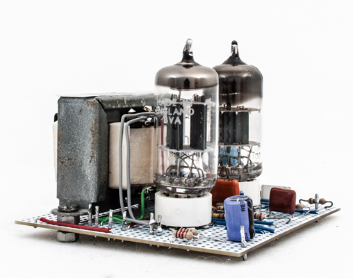
The Bravo Audio amp on the left with the new amplifier on the right. Both are 80 mm square.
The first part of the design was to build the output stage. The ECC82 has a maximum anode dissipation of 2.5 Watts per anode. At 250 Volts HT this is a cathode current of 10 mA but as maximum output was not required the output stage is run at 8 mA per triode with 250 Volts HT. The biasing allows the stage to run in pure Class A. Small modern components were used throughout and two 1.2 kΩ resistors in parallel gave the 600 Ω required for the cathode resistor. The cathode resistor is bypassed with a 47 μF electrolytic. The grid to ground resistors are 150 kΩ each. Coupling from the previous stage is via a 0.1 μF capacitors.
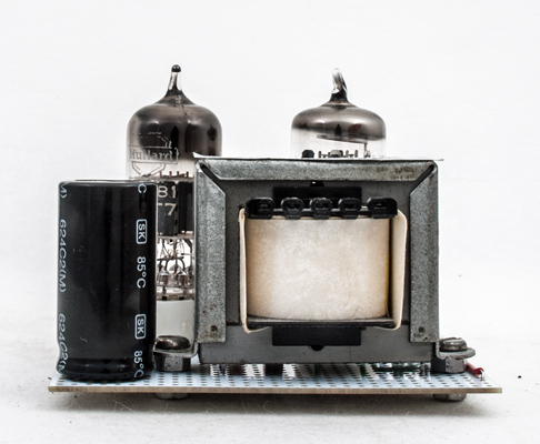
The 600 mW amplifier. The ECC82 is at the back.
For a hybrid design with a valve output stage, the voltage amplifier and phase splitter needed to be solid state. The breadboard version used an OPA134PA ultra low noise op-amp and a DRV134PA audio differential line driver to produce the two signals for the valve grids with 180 ° phase difference. The amplifier worked well and to improve the transfer characteristic, negative feedback from the transformer secondary to the op-amp was employed. A 220 pF capacitor shunted across the feedback resistor offered sufficient frequency correction.
The amplifier testing was done with a Mission Audio two-way reflex bookshelf speaker. The input was from the line out port of a computer sound card. Volume control was provided at the computer. The test environment is 7 m x 4 m and listening across the room was quite acceptable. Sitting at the bench next to the speaker required the volume to be set much lower. The author's standard listener (daughter) rated the overall sound from the amplifier as excellent.
The breadboard version stayed as a lash-up until a couple of weeks ago. Two more of the FireFly output transformers will allow for the hybrid design to be built as a stereo unit. Special quality 13D2 double triodes are to be used in the output stages.
For the amplifier presented here a valve pre-amp and phase splitter was used. Going back to basics a cathodyne phase splitter using a single triode was planned. The Valve Wizzard produces excellent information and the fixed bias design chosen comes from his web book.
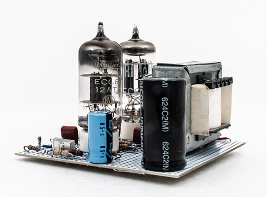
The cathodyne phase splitter on the right with voltage amplifier on the left.
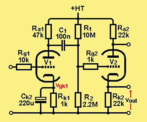
The circuit was built as the diagram below with the exception of provision for negative feedback to the input triode. The cathode has an 820 Ω resistor shunted by the 220 μF electrolytic in series with a 180 Ω resistor to ground.
The plan is to run the amplifier from a 12 Volt DC supply. A switched mode DC-DC converter limited to 700 mA feeds the heaters at 6.3 Volts. The HT will be supplied from another DC-DC switch mode unit running at 120 kHz. However, for the testing phase the 250 Volt HT was taken from a Heathkit IP-17 regulated HT power supply.
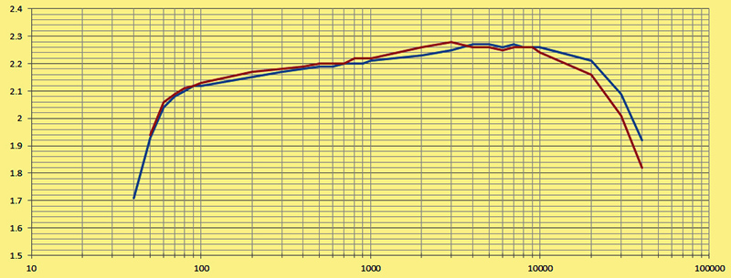
Response of the amplifier. Output voltage across 8 Ω plotted against frequency. The red line is for an ECC83 and the Blue line is for an ECC81.
A non-inductive eight Ohm load was made from two power resistors in series and a parallel resistor chosen to trim the resistance to eight Ohms. The test signal was from an AFG-2112 function generator and the signal monitored on a Tektronix TDS 2012 dual trace oscilloscope. The input sine wave signal at 1 kHz was increased until the output trace showed signs of clipping above 270 mV RMS. Switching to spectrum analyser mode the input was backed off to minimise the third harmonic.
The output stage is cathode biased and thus not designed for constant sine wave input. The function generator was set to frequency with the output off and signal was applied to the amplifier for only as long as was required for the scope to measure the output voltage.
The graph has two traces as both the ECC83 and ECC81 were tested in the circuit. Subjectively the ECC81 had the more pleasing sound and was left in place.
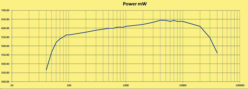
Power output plotted against frequency with 270 mV input.
Adding negative feedback was the final part of the project. The open loop gain is low and so only a small amount of feedback was considered possible. Approximately 3 dB of feedback was added via a 2.2 kΩ resistor. This reduced the output at 1 kHz from 2.23 V RMS to 1.54 V and increased the input required for maximum output to 0.45 V RMS. To counter the rising frequency characteristic of the amplifier a series of capacitors across the feedback resistor were tried. A value of 22 nF was chosen. At 10 kHz the reactance is 724 Ω reducing the feedback resistor to an effective value of 544 Ω giving greater feedback and flattening the response curve.
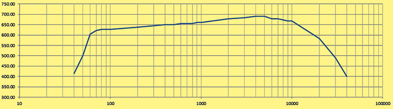
Power output of amplifier with feedback. 450 mV input and no distortion of the oscilloscope trace.
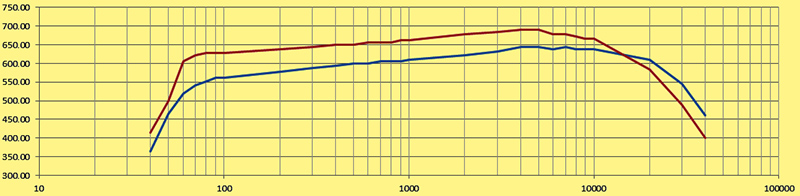
Before and after. The red trace is with feedback applied.
Subjectively the amplifier sounds fine to my ears. As my hearing decreases with increased frequency the slight treble boost is not noticeable and a response above 10 kHz is academic.
The rear of the amplifier. The 47 μF capacitor is across the HT.
Initially the 220 μF cathode bypass capacitor was too close to the valve and so it was moved to the edge of the board.
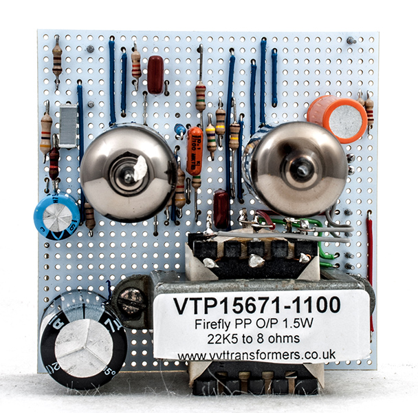
The board from above. The transformer used is the VTP15671-1100 from VVT Transformers [★] no longer trading. The Vero pins used for the external connections are (left to right): signal in, ground, heater 0 Volts, HT+, heater 6.3 Volt and finally the speaker connections next to the transformer.
With the HT raised to 300 Volts the ECC82 runs at 20 mA cathode current and just exceeds the anode dissipation limit. The output power is then 1 Watt and the volume of the 1 kHz tone is almost painful.
| 