|
The first of a series of articles, specially written for the constructor who wishes to use his radio receiver and loud speaker for the reproduction of gramophone records. The author also provided a series of hints and tips on how to a pick-up correctly.
Have you ever realised what vastly improved results you can obtain by playing your gramophone electrically? The modern gramophone record is produced in a studio of much the same type as that used by the BBC for broadcasting their ordinary programmes. A microphone amplifier is employed, and in consequence the records sold to-day are remarkable for their depth of tone provided the apparatus used for reproducing them can do justice to this improved means of recording.
Improved Reproduction.
Those who have a good cone loud speaker capable of responding to the lower musical frequencies, and a well-designed amplifier, can take advantage of this new improved method of electrical recording by using their gramophone and wireless amplifier in conjunction with a device known as a gramophone pick-up.
A pick-up is simply an arrangement which is used in place of the existing reproducer. It fits into the tone arm of the gramophone in exactly the same way as the ordinary sound box, and one uses it just as if one intends to play the gramophone in the usual manner. The same needles are used, and,in fact, the pick-up is simply a device which automatically transfers the vibrations from the sound channels on the record to the wireless amplifier in the form of small voltages across the grid and filament of the low-frequency valve. Two wire's have to be taken from the terminals on the pick-up to the grid and filament of one of the LF valves in the existing set.
Easily Adapted
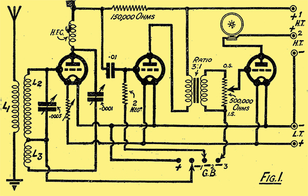
It is quite easy to adapt any set for use with a pick-up. In Fig. 1 I have shown a very common type of circuit, namely, a detector and two low-frequency valves, the first being resistance and the second transformer-coupled. This combination, as readers know, is capable of giving very good reproduction, and there is no reason at all why it should not be used in conjunction with a gramophone. As will be seen, the detector functions on what is usually termed the anode-bend method.
Let us suppose that three plug-in coils are used, that is, L1 the aerial coil, L2 the secondary, and L3 the Reinartz reaction coil. One side of L2 is normally connected to a point on a small grid-bias battery or direct to LT negative, and the other side of this coil is joined straight to the grid of the detector valve. All that we have to do then is to remove this coil from L2 and to connect our two pick-up leads direct to the plug and socket of the coil holder. This can be done by means of an ordinary coil socket such as one obtains for the purpose of mounting onebs home-made coils. The first valve will then function as a low frequency amplifier, and the only slight alteration which may be necessary is a reduction in the grid-bias value to the first valve. In most cases 1.5 Volt will be correct. If a six-pin coil is used, then it is only necessary to connect the pick-up to the two sockets which connect up with the pins to which the ends of the secondary coil are joined. No other modification is necessary.
Inserting a Switch.
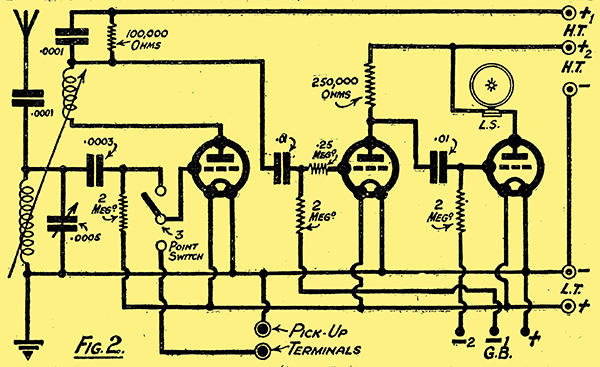
Fig. 2 shows another very popular type of circuit. In this case a grid-leak-and-capacitor detector valve is employed in conjunction with two resistance coupled low frequency valves. The simplest method of altering this circuit to take a gramophone pick-up is to connect up a single-pole double-throw switch so that in one position of the switch the set is arranged to receive broadcasting, Whilst in the other position the first valve is connected so as to operate as an LF amplifier. The connections are very simple, as will be seen from the figure. The grid of the first valve is joined to the centre point on the switch. The lead from the grid leak and condenser goes to the other side of the switch, While one terminal of the pick-up is joined to the remaining contact. The other terminal on the pick-up can be taken direct to LT. negative. The leads from the switch to the pick-up could be taken to an ordinary telephone jack mounted on the panel of the set and the pick-up plugged in when it is desired to use the gramophone. Both of these circuits will give excellent reproduction and extraordinarily good volume when used in conjunction with a moderately sensitive gramophone pick-up.
Special Adaptor Plugs
Of course, in the case of such gramophone attachments as the Amplion Vivavox, and others which are designed to plug direct into the detector socket in the existing set, no alterations such as those just described will be necessary. It will therefore be seen that to use a gramophone pick-up is the easiest thing in the world, and those who have never tried to combine radio and the gramophone may do so with the knowledge that they will not be disappointed in the results.
Pick-ups we have Tested
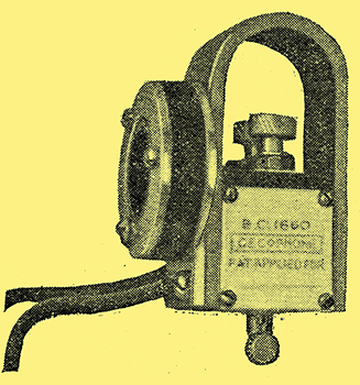
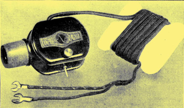
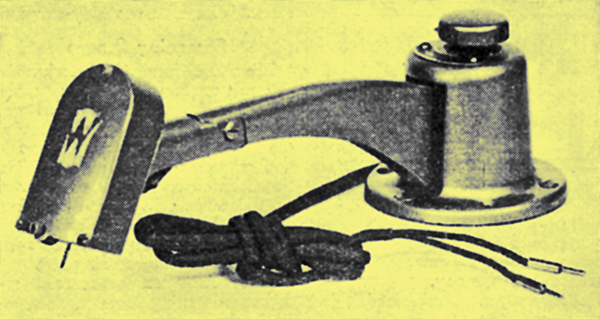
We have recently had the opportunity of giving an extended trial to two gramophone pick-ups marketed by the makers of well-known loud speakers. One of these is the Woodruffe and the other is the Amplion. The Woodruffe pick-up, a photograph of which appears below, is handled by the makers of the well-known Celestion loud speaker.
The price is somewhat high - it retails at four guineas, but the results are so good that one feels that one is obtaining ample value for money. The pick-up is supplied in two fittings - one to suit the Columbia and the majority of tone arms, and the other to suit the HMV gramophone. The electrical portion of this component is of fairly conventional design - that is to say, a high- resistance permanent-magnet winding is employed, the movement of a damped armature in sympathy with the sound channel on the records giving the necessary voltages across grid and filament to operate the amplifier. The armature is heavily damped with rubber, and on test no marked resonance peak could be detected.
The Woodruffe Pick-Up
The pick-up is not what one might call highly sensitive, and in order to get maximum results from a cone or moving-coil loud speaker it is advisable to employ three stages of resistance-coupled LF or two of resistance and one of transformer. The volume, however, can be increased very greatly if one cares to invest in a Marconi Ideal 8:1 ratio transformer, and to insert this transformer between the pick-up and grid and filament of the first LF valve. The transformer is, of course, by no means essential, and, as stated above, excellent results can be obtained with three ordinary resistance - coupled stages, or, in fact, with any good amplifier of a type designed to give even amplification over a wide range of musical frequencies.
The Woodruffe pick-up is stated to be one ounce lighter than the sound-box used by a well-known gramophone manufacturer, and on the score of weight alone readers need not be afraid that undue wear of the record will occur. The results are so good that it is difficult to find any point to criticise. Possibly the method of adjusting the armature in order to obtain the required degree of sensitivity is a little coarse. In addition no attempt has been made to protect the fine wire magnet windings, and in consequence one is rather liable to damage the windings when handling the pick-up. These, of course, are quite small points, and the component can be thoroughly recommended.
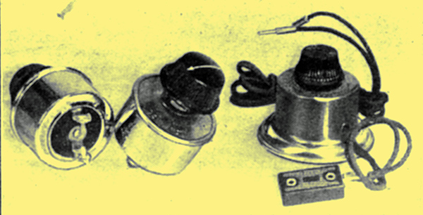
The Amplion Pick-Up
The question of radio and the gramophone has evidently been tackled very seriously by Messrs. Amplion. This firm have designed their pick-up to be plugged direct into the detector socket of any existing receiver. The device consists of three parts - the pick-up it-self, a. volume control, and a special plug to be inserted into the detector valve holder on the set. The pick-up is a most impressive-looking job, and is attached to the tone-arm by means of a rubber collar, or in the case of the Columbia machine, a special-split sleeve which fits inside the collar. The magnet windings are protected by a strongly-made Bakelite case. In spite of this, the pick-up is quite light in weight. Two leads from the pick-up go to the volume control, which is intended to be placed near the gramophone itself. As evidence of the amount of thought expended by the makers in designing this component, it is interesting to note that the volume control is enclosed in a heavy metal casing, this weight being sufficient to keep it in position without any necessity for securing-screws. A long flexible lead goes from the volume control to a plug, and the procedure is as follows: The purchaser first finds out which is the negative socket of his detector-valve holder. He then connects the tag with the white strand to the pin of the plug which makes contact with this negative socket. The plug is then inserted in the valve holder, after which the detector valve is inserted into the four sockets on.the top of the plug adaptor. It will, therefore, seen that no alteration to the existing receiver is necessary in order to use the gramophone attachment.
On test the device gave excellent results and the sensitivity is quite high. The pick-up is well damped and there are no unpleasant peaks. Moreover, the volume control really works, and the strength of signal can be decreased to a whisper. As one would expect from a firm of such high standing as Messrs. Amplion, the general finish of the attachment is extremely good, and the impression gained is that it is a component of the highest quality. We have no hesitation in recommending it.
As we go to press we have just received a specimen of the new Lissen pick-up which sells at the very attractive figure of 15/-. This unit is of pleasing finish and neat design and promises to be remarkably good value for money. We have not yet completed our tests on this component but propose to give a full report in our next issue.
We stated in our review last month that we had just received one of the new Lissen gramophone pick-ups for test and report. We have now had an opportunity of making a thorough examination of this little component.
One of the lowest-priced pick-ups on the market is the Lissen shown above.
The Lissen pick-up is not unlike a telephone ear piece in appearance. It is of the permanent magnet type, the windings being of high resistance. A very stiff armature is pivoted at one end, and arranged so that by means of a knurled adjusting screw its distance from the magnet, and consequently its sensitivity, can be adjusted easily and quickly.
It is evident that some care has been expended in the design, and it is apparent that efforts have been made to render the arrangement as free from resonance as is possible. A neat aluminium cover protects the internals and prevents damage to the delicate magnet windings, and the component is quite light in weight.
On test with three stages of resistance coupled low frequency amplification, and in conjunction with a moving coil loud speaker, the pick-up showed good sensitivity and, considering its remarkably low price, namely, 15/- is certainly excellent value for money.Those to whom price is a consideration should certainly secure a practical demonstration of this component, and we can assure them that they will be surprised at the results it gives.
Very Sensitive
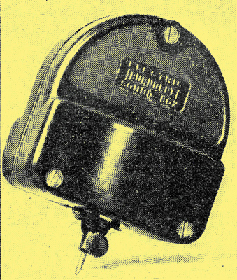
We have also received for test the pick-up made by the General Electric Company, Ltd. Here, again, the device is of the permanent magnet type, the magnet windings themselves being entirely enclosed in a very neat aluminium case, a substantial horse-shoe magnet being used to form the framework upon which the component is built-up.
The Gecophone pick-up.
The whole component is extremely rigid, is well finished, and gives one the impression of being very serviceable. On test it was found to be very sensitive, and quite up to the standard of the other pick-ups with which it was compared. There were no noticeable resonance peaks, and both the high and low notes were faithfully reproduced. The device can be well recommended.
The Pick-Up in Practice
Each month brings forth further progress in the art of mechanical reproduction of music. Gramophone manufacturers themselves are conducting experiments in the electrical reproduction of their records. I believe that within a year or so, all of the best quality gramophones will incorporate some form of electrical pick-up and amplifier, instead of the ordinary sound-box.
There is already one excellent example on the market, namely, the Panatrope, which utilises a valve amplifier and a moving-coil loud speaker unit. Of course, the Panatrope is rather expensive, but I believe that it will be possible for manufacturers to turn out a first-class gramophone employing a pick-up and some form of cone loud speaking device which will be sold at a reasonable price.
Radio enthusiasts, however, are in a very advantageous position, because they already have their amplifier, batteries, etc., and there is no reason why they should not obtain results just as good as anything the gramophone manufacturers can turn out, and, moreover, at a lower cost, because they can utilise their existing radio parts.
Generally speaking, any modern amplifier designed to reproduce the lower frequencies will give excellent results with a pick-up. Most of the up-tho-date wireless sets utilise either resistance capacity coupling or resistance transformer coupling on the low-frequency side, and both arrangements can be used successfully.
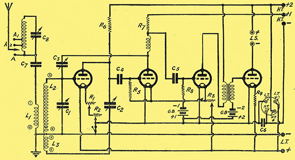
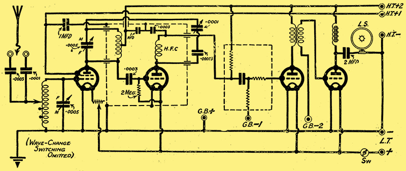
The theoretical circuit diagram of the Business Manbs Four, the full description of which appeared in the February number of the Wireless Constructor.
The Business Manbs Four, which was described by Mr Harris in the February issue, can be easily adapted for use with a pick-up. The theoretical diagram has been reproduced for the benefit of those who have constructed this popular receiver, and-who are interested in the electrical reproduction of gramophone records.
A Plug for Pick-Ups
The easiest method is obviously to employ one of the pick-ups which can be plugged straight into the detector socket, such as the Amplion, and others. In this case, no modification would be necessary, the adaptor socket being plugged straight into the second valve holder of the Business Manbs Four.
Alternatively, a plug and jack could be used. The panel could be drilled to take an ordinary open-circuit telephone jack, the two contacts being connected to the grid and negative filament of the detector valve. The HF valve could be turned out by means of the variable resistance and the pick-up plugged straight into the jack.
One other modification would be necessary, and that is the detector grid leak R5 would have to be removed from its clip, otherwise the grid of the first valve would be at a positive potential. Of course, this could also be carried out by switching, and next month I shall show how a switch could be incorporated in order to change straight over from gramophone to radio and vice versa.
I am of the opinion that one of the simplest and most easily handled amplifiers for gramophone use is a straight three LF resistance-coupled.
It is cheap, and very rarely suffers from that bugbear, LF oscillation.
The values I prefer are as follows:- First stage, anode resistance 200 kΩ, second stage, anode resistance 100 kΩ and third stage, also 100 kΩ. Coupling condensers of 0.02 μF and grid resistances of 1 MΩ give very good results.
These values give what may be termed medium amplification, that is to say, the step-up at each stage is not very great, but the quality is excellent. Three stages will give plenty of volume with any of the pick-ups I have tried.
The pick-up leads can be connected straight across the grid and negative filament of the first valve, which may be one of the so-called HF type (impedance 20-30 kΩ, magnification 20), and the second valve may be of similar type, with 1.5-3 volts grid bias. The next valve can be a small power valve (impedance 8-10 kΩ), and the last valve a super-power type.
The same HT can be employed on all the valves and should not be less than 120 Volts.
Recommended Records
I have been asked what are the most suitable records for use with a pick-up. In general I think that practically all of those which have been electrically recorded will be quite suitable. I have used the HMV, Columbia, and Brunswick with excellent effect.
Organ records come through wonderfully well on a cone loud speaker. None of the moderately priced gramophones seem to render the bass to the same effect, and once a pick-up has been tried in conjunction with a good amplifier one never wishes to return to the ordinary sound-box again.
Personally, I use the ordinary steel HMV needle, and I always change it each time a new record is played. If the pick-up is reasonably sensitive a medium tone seems to be the best.
Further Experiments
I have recently been conducting experiments with two transformer-coupled LF stages used in conjunction with a pick-up, in order to see whether the reproduction showed any improvement upon the ordinary gramophone and sound-box.
If two really first-class transformers are employed, the quality is surprisingly good. If the instruments are of a mediocre type the result is a loss of the lower frequencies, thus giving a high-pitched effect, and the benefits of electrical reproduction are lost.
The chief trouble with a couple of transformers is the tendency for LF oscillation to occur. The greater the efficiency aimed at, the more difficult becomes the task of maintaining fairly even amplification of the musical frequencies. LF oscillation, in its worst form, appears as a continuous howl. When this happens it is quite obvious to even the veriest novice that there is something seriously amiss. There is another type of LF trouble which is far more difficult to detect, and that is, certain musical notes are amplified out of all proportion. to the others. The amplifier, so to speak, is peaking on certain frequencies, and this has the effect of spoiling reproduction.
Combined Coupling Easier
For this reason always consider that it is a much easier matter for the average listener to obtain first rate results with a combination of resistance and transformer coupling, because there are so many little snags in getting two highly efficient transformers to work properly together.
Of course, in the hands of a skilled experimenter, wonderful reproduction can be obtained with two, or even three, transformers, but it is essential for all coupling and other effects to be eliminated, and it is this which renders it so difficult for the average constructor to do justice to the transformers at his disposal. Therefore, for gramophone reproduction I strongly recommend either a combination of resistance and transformer, or pure resistance coupling.
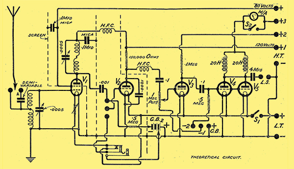
This is a very good circuit for combined gramophone and radio work, the change-over being easily made by means of the simple switch shown.
For the more ambitious listener the circuit shown takes a lot of beating. As will be seen it consists of a screened-grid HF valve, followed by a detector and two RC stages.
It is an ideal arrangement for those who wish to combine high quality from the local station with realistic gramophone reproduction.
Switching Over
The change-over from radio to gramophone can be made by throwing over the single-pole change-over switch, and plugging in a telephone jack to which the two pick-up leads are connected. This operation converts the anode rectifier into an LF valve by altering the grid bias to its correct value for the purpose, and thus three stages of the RC coupling become available for pick-up work.
Volume is controlled by means of a1 1 MΩ potentiometer, such as the GEC, and the coupling condensers are 0.1 μF mica. The object of connecting the two output chokes in parallel is to reduce the voltage drop across the windings - an important factor with two paralleled valves working on high anode voltages and also tor minimise the chances of an excessive loss of inductance such as might be the case if only one choke were employed.
The jack shown is an Igranic P56, but only four of the contacts are used, the second from the bottom and the top one being left blank. The action of inserting the telephone plug switches out the HF valve. As to valves, I suggest an HF type, impedance 20 kΩ, amplification factor 20, in the detector socket, an LF valve in the V3 socket, and two super-power type valves for V4 and V5. For moderate volumes V3 can be an HF type valve, but there is a danger of overloading on very strong signals. The dotted lines indicate copper screening, and these are essential if perfect stability is desired.
In addition, the baseboard has a copper floor which extends to the LF side. It is advisable to use astatic coils in order to reduce screen losses, and these may consist of 70 turns wound in two halves of 35 for the aerial coil, and 80 turns wound in two equal halves for the anode coil. Each half is wound the opposite direction, 9/38 Litz wire being a convenient gauge; 3 in. diameter formers are suitable.
In my article last month I promised to give details of a simple switching scheme which could be used in the Business Manbs Four, so that a rapid change-over might be made from radio to gramophone. I find that the method I intended to employ necessitates a slight modification to the layout; and I am, therefore, holding it over in the hope of devising an alternative method not involving this alteration.
From time to time one hears stories regarding the wear on records brought about by the use of gramophone pick-ups. I have been using a number of HMV and Columbia records for some time in connection with my experiments, and I can honestly say that although I have played each record very many times, I have not as yet been able to detect any deterioration in the reproduction.
Possibly the use of half tone needles is a help. I always think that the loud and extra loud needles must tend to tear the records up to a greater degree.
Home-Made Gramophones
A friend of mine asked me whether it would not be possible for him to make up his own gramophone attachment in order to avoid having to purchase the complete outfit. This is really quite a simple matter.
One only requires a clockwork motor, turntable, and tone arm. The motor and turntable can be mounted on a piece of plywood supported on four legs. The tone arm is then placed in a convenient position, and the arrangement is ready for use. Of course, if one desires, the attachment can be enclosed in a cabinet, but this naturally adds to the cost. All the parts can be purchased at any of the large stores, or they can be obtained secondhand. If price is not the primary consideration, I recommend the use of a double-spring motor in preference to one of the single-spring variety. One does not wish to have to re-wind the motor after each record. In addition, the speed is apt to be more constant with the double-spring type.
The Electric Motor
For those who have the electric-light mains there is also that excellent little motor and turntable which is marketed by the General Electric Company. With this it is only necessary to make connection to the nearest wall socket with the aid of a flexible cord. Moreover, the current consumption is very low, and the running costs should be negligible. An electric turntable of this type is a real boon to those who have the mains, since the trouble of always having to wind up the motor after every two records or so is completely eliminated.
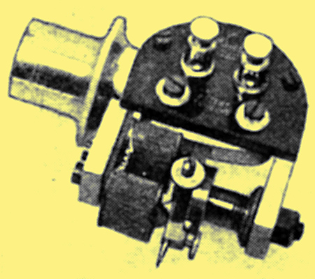
Igranic Phonovox
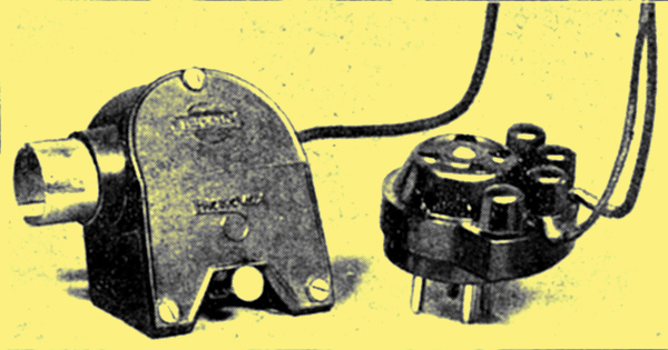
The Phonovox (Igranic) pick-up, with special plug-in adaptor.
We have received for test one of the Igranic Phonovox gramophone pick-ups. The pick-up itiself is an exceedingly well made device, which operates on the permanent-magnet system. The working parts are neatly enclosed and protected by a black bakelite casing and a ferrule is fitted which is so arranged that the pick-up may be used with all types of tone arms. When fitting the Phonovox to the tone arm, the makers point out that it is essential for the pick-up to be at approximately the same angle in relation to the surface of the record as was the needle in the original sound-box.
This can easily be done in the case of the Phonovox by setting it so that the bottom surface parallel with the record.
On test the pick-up proved to be very sensitive, so much so that it was possible to use 'half-tone' needles with advantage.
Good Reproduction
The device showed no tendency to chatter unduly, and the reproduction obtainable, in conjunction with a three-stage resistance amplifier and a moving-coil loud speaker, was good. When compared with pick-ups of other types, the Phonovox seemed to emphasize the scratch a little more, but this may be due to the fact that there is cut-off on the higher frequencies with this component. The pick-up is good value for money (the price is 37s. 6d.) and can be recommended.
It is interesting to note that the Igranic Co. also supply a plug-adaptor and volume control for use with their pick-up.
Adaptor Provided
Those who do not wish to modify their existing receivers can utilise the low-frequency side of their sets by simply plugging the adaptor into the detector-valve socket in place of the detector valve itself. Full details of how to do this are supplied with the component.
Readers are still asking me what needles they should use for radio-gramophone work. The reply is that it depends upon the sensitivity of the pick-up and the amplification given by the LF stages. Where possible, I much prefer a 'half-tone' needle, because I think that wear on the records is minimised, and in addition the background 'hiss' is less.
If, however, the pi.ck-up is rather insensitive and the amplifier one with only moderate magnification, the obvious thing to do appears to be to employ a loud needle.
I have tried fibre needles and I do not like them for this type of work so well as the ordinary steel pattern. Please remember that it is just as important to use a new needle in the pick-up each time the record is changed as it is when employing the standard sound-box.
A troublesome fault has recently developed in my amplifier. As I have previously mentioned, it consists of three resistance stages, the values of the anode resistances being 150 kΩ, 100 kΩ, and 80 kΩ respectively. The grid leaks are each 1 MΩ and the coupling condensers 0.1 μF. The output circuit is choke coupled and the whole amplifier has been most carefully designed and has always been perfectly stable. During the last week or so there has been a marked tendency for the amplifier to oscillate at a frequency above audibility.
A Simple Remedy
The only method of detecting the trouble is to place a milliammeter in the plate circuit of the second valve, and to observe the increase in plate current when oscillation occurs. The fault is in all probability the result of a partially sulphated cell in the HT supply which is fed from a battery of accumulators giving a total of 300 Volts. As can be imagined, with 150 small cells to examine, it is no easy matter to find out just which cell is likely to be a little 'off colour', but readers who are having similar trouble with their amplifiers should try a grid-stopper of about 100 kΩ in series between the coupling condenser and the grid of the valve.
In the case of the amplifier mentioned this has proved to be a very effective remedy, pending a complete cure by removing the cause of the instability.
The old question as to what is the most satisfactory type of amplifier to employ for very large volumes keeps on cropping up.
Such cases occur when sufficient strength to fill a large hall for dance purposes and so forth is needed.
Well I am rather of the opinion that in these days of super-quality transformers it is solely a question of HT.
AC Advantage
For instance, if the mains are handy, and especially if they are AC, it is quite easy to hitch up a mains HT unit designed to supply a high voltage in the neighbourhood of 300 Volts or more, and to employ a straight resistance-capacity or resistance transformer amplifier of conventional type.
The only point to bear in mind is that large valves of the LS5 type should be used, because ordinary valves are not designed to stand up to such high HT voltages. It is also advisable to connect two or more in parallel in the last stage. If, on the other hand, the only HT available is that obtainable from low-voltage DC mains, or from batteries, then I think that push-pull amplification has certain advantages.
Push-Pull Amplification
So, in cases where the maximum HT voltage available is not greater than 200 Volts, I would suggest a good push-pull output stage, together with low-impedance valves having a long straight characteristic and a small amplification factor. Of course, these remarks only apply in cases where it is desired to fill a hall or to handle very large volumes.
For ordinary domestic purposes, the usual HT voltages of 120 or so are quite adequate, and it is only when something more than this is required that it becomes necessary to pay special attention to points in the design of the amplifier and to the HT supply.
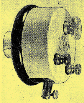
Loewe pick-ups
This is the Loewe gramophone pick-up which Mr Johnson-Randall deals with below.
We have received for test one, of the new Loewe pick-ups. This device has been placed on the British market at the low cost Of 18s 6d.
It is of the permanent-magnet high-resistance type, and operates on a 'semi-balanced' armature principle, that is to say, the armature is placed equidistantly between the two magnet poles. Every endeavour has been made to damp out resonance by providing stout rubber buffers at vital points. The pick-up is light in weight and exceedingly compact. The magnet assembly is well protected by a neat Bakelite casing and the whole arrangement is sturdy and strongly constructed.
On test the pick-up gave very good results and there was a marked absence of 'dither', this tending to show how well the resonance has been damped out. In addition the higher frequencies were present in their correct proportion (aurally), and the device is certainly excellent value. It can be recommended to those who desire a good-quality pick-up at a moderate price.
Battery Consumption
This month I want to talk about the HT consumption, of gramophone amplifiers and HT batteries in general.
Now it is highly probable that the amplifier used is part of the ordinary domestic radio equipment. There are not very many readers who care to run separate amplifiers, this partly for economical reasons and partly because there is no difference between a gramophone amplifier and any other valve magnifier employed for the reproduction of music.
Hence my remarks on HT consumption will apply equally to the LF side of radio receivers.
Most gramophone amplifiers consist of either a combination of resistance and transformer coupling, or of pure resistance-capacity coupling.
Suppose we assume an ordinary straightforward two-stage amplifier, consisting; of a resistance stage followed by an LF transformer. The anode current taken by the first valve will be quite small, because of the limiting effect of the resistance, and we can take it that it will not exceed half a milliampere. The second valve will have the primary winding of the transformer in series with the anode, and if it is a good modern low-ratio instrument the plate current for this valve will not be greater than 3 or 4 milliamperes, owing to the effect of heavier currents on the transformer characteristic. The last valve will be a super-power, and with 120 -150 Volts HT it is probable that the anode current will be in the neighbourhood of 20 milliamperes, or perhaps a little less.
Now, the sum of these currents will be, roughly, 24 milliamperes, and it is quite useless attempting to employ a small dry HT battery of the 'Popular' type. These batteries are really intended for the smaller sets, and the current taken should not generally exceed 5 milliamps.
Large-Sized Cells Required
If dry batteries are to be used economically for an amplifier designed to give high quality it is essential to choose those of the 'super' type, Which have large-sized cells. Apart from the fact that the smaller cells cannot stand up to a current drain of 20 milliamps or more, the internal resistance of a small-sized battery tends to rise very rapidly, and this in turn frequently causes low-frequency howling and distortion.
Those who have charging facilities will be much better off if they use accumulators, or, alternatively, they can employ the electric-lighting mains in conjunction with a suitable mains HT unit. In the case of HT accumulators, for currents in excess of 20 milliamperes it is preferable to choose the 5,000 milliampere-hour type of cell, since the smaller sizes will need rather frequent charging if the amplifier is in constant use.
Now what about those amplifiers designed for large Volume?
These will usually have three LF stages, and in most cases the last stage will have two low-impedance valves connected in parallel.
Paralleled Valves
We can assume an average anode current of 5 milliamps for all valves excepting the two in the last stage. The paralleled valves may take anything from 30 - 50 milliamperes, according to the HT voltage, and in consequence it is hopeless to expect dry batteries to supply such a heavy. current demand. In these cases accumulators or a mains unit are the only solution, and of the two there is no doubt that the mains unit is by far the more economical. In choosing the mains unit it is as well to provide for a voltage of 200 or more if possible.
This is an easy matter with AC mains, but in the case of DC mains it is not practicable to step-up the voltage except by expensive means, and the constructor may be limited to 120 Volts maximum. If very large volumes are required it may be worthwhile trying push-pull amplification when the HT voltage is limited.
Volume Control
One of the troublesome problems in pick-up work is that of controlling volume so that the last valve is not overloaded on loud passages.
It seems to one that a strength control of some kind is more necessary in gramophone work, because in radio a certain amount of attention is given to this point at the transmitting end, and those sudden increases in strength so liable to cause 'blasting' are not so frequent.
Starting at the pick-up itself, perhaps the simplest procedure is to get to know the records and to choose the needles accordingly. There are, for instance, soft, medium, loud, and very loud needles, and quite a lot can be achieved by inserting a suitable type in the pick-up. Of course, many makers supply a volume control suitable for use in conjunction with their pick-ups, and in these cases there is no-need to adopt any special method of cutting down the strength.
Use of Potentiometer
One of the best and simplest methods of controlling the volume from a pick-up is to utilise a variable high-resistance like the one shown to the right.
If no control is available, however, it is always advisable to adjust the small screw usually provided on the pick-up for the purpose of increasing or decreasing the sensitivity of the device. This screw in most cases alters the distance between the armature and the magnet pole faces.
Alternatively, one can obtain a 500,000 Ohm potentiometer and connect this across the pick-up terminals. Normally, these terminals will be joined, one to the grid of the first LF valve, and the other to LT - or GB -.
Connecting Up
In connecting the potentiometer, the lead from the pick-up to the grid of the valve should be disconnected, and the grid joined direct to the arm of the potentiometer. The connections then are: One terminal of pick-up to LT - or GB - and to one of the outside terminals of the potentiometer. The remaining outside terminal of the potentiometer goes to the other terminal on the pick-up, and the centre terminal or moving arm of the potentiometer goes to the grid of the valve.
Rotating the potentiometer arm will give the desired variation in volume. The potentiometer chosen must have a high-resistance, not lower than 500,000 Ohms, and should be non-inductive. There are several suitable types on the market, among which is the 1 Megohm potentiometer marketed by the GEC.
Records should be run at a certain specified speed for the best results. The correct speed in revolutions per minute is marked on the record. A simple method of determining this speed is as follows:
Place a chalk mark or a small spot of white paper on the edge of the disc. Start up the motor with the pick-up in position and the needle bearing on the surface of the record in the normal manner.
Then count the number of times the mark passes a given point in a quarter of a minute, and multiply this result by four. This will give the number of the revolutions of the disc per minute.
Stopping Howling
It is useless running the record 'light', i.e. without the needle bearing on the surface, because the motor may slow down a little directly the 'load' of the pick-up and tone-arm comes into play.
If various readings for different adjustments of the speed regulator are obtained, the turntable can be calibrated, and it is then a simple matter to adjust the regulator to give any desired number of revolutions per minute.
Recently I was informed of a method of stopping howling in an amplifier which became unstable whenever a pick-up was used.
The amplifier, incidentally, was quite OK for radio reception.
If a pick-up was connected up in the usual manner, the LF stages immediately showed a tendency to oscillate. My informant stated that when he 'earthed' the tone-arm of the gramophone by connecting it to LT - the howl immediately stopped. This is certainly a tip worth trying, but, of course, it would not apply to every case. For instance, it is doubtful if 'earthing' the tone-arm would have any beneficial results in cases where the pick-up is insulated from it by a rubber sleeve.
It is surprising how much trouble his caused by running the loud-speaker leads too close to the leads from the set to the pick-up. There is a tendency to place the loud speaker near the gramophone turntable and the two sets of leads are apt to become intertwined. Thus we have the amplified low-frequency impulses in the output circuit of the amplifier being fed back to the first LF valve via the pick-up leads, and this way low frequency oscillation is frequently set-up. The symptoms are violent howling or chronic distortion without howling. When trouble of this kind is experienced it is advisable to see whether these two sets of wiring are well separated before looking elsewhere for the fault.
A Second Possibility
This is particularly the case when the amplifier is part of a broadcast receiver, and functions quite satisfactorily for the reception of the ordinary radio programmes, bursting into violent oscillation directly the pick-up is plugged in.
Of course, this is not the only possibility.
In the majority of cases, when the pick-up is plugged in an additional LF valve is brought into operation (usually the detector which is arranged to work as an LF stage) and there is consequently a slightly increased tendency to self-oscillation and if the remaining stages are not quite up to the mark the amplifier may 'spill over' and howl.
Electrical Turntables
Those who have purchased electrical turntables may be having a spot of bother over the speed regulation. There is on most of these turntables a small adjuster and this can be set to give any required speed. The revolutions' per minute can be determined as described in last monthbs article. It must be remembered that these turntables cannot be pre-set owing to the fact that a slight variation between the voltages of different supply mains will alter the speed. Therefore, each turntable should be adjusted to suit the mains with which it is to be used. While on this subject of LF oscillation the old bugbear of 'motor-boating' must not be forgotten. This form of LF trouble has been very difficult to overcome, but I am glad to see that there is a number of anode-feed units and resistances which are being placed on the market with the object of obviating troubles of this nature. These anode-feed resistances are very useful because it is possible to employ one HT voltage throughout, applying the maximum to the last valve (or valves, if there are two in parallel) and cutting it down with the feed resistances to suit the remaining stages.
This is anther step in the light direction towards the simplifying of set design and the prevention of those annoying troubles which so often cause distortion and general 'fedupness' on the part of the home constructor.
We have received one of the new Burndept pick-ups for test. It is an extremely well made component functioning on the electromagnetic principle, the permanent magnet being completely protected by a neat black moulding of insulating material.
A Well Made Device
The Burndept 'Electrical Sound box'.
The two terminals to which are attached, the pick-up leads are also mounted on the case.
The device can be obtained complete with volume control, and this is recommended, to those who have no means of adjusting signal strength incorporated in the set.
On test the pick-up gave very good results, and there was a marked absence of chatter. The bass comes out very well, provided a suitable amplifier and loud speaker are used, and there is no noticeable loss of the higher frequencies.
The price of the pick-up is 20/- and it can be well recommended.
Record Wear
I receive quite a number of queries concerning record wear, and I am afraid that I can only inform my querists that some pick-ups do to produce fairly rapid wear. There is still a lot to be learnt about the design of gramophone pick-ups, and in some cases makers in their eagerness to ensure high-quality reproduction, seem to have overlooked the important question of wear on the record.
We hope to be in a position to publish details of some experiments on this question, and also that of balancing the tone arm, in the near future.
Radiano Four
Mr Percy Harrisbs new 'Radiano Four' receiver will undoubtedly be one of the star designs of the coming season. No doubt readers will wonder whether they can use a pick-up with the set, when required.
For the benefit of such readers I have reproduced the theoretical circuit of the Radiano Four.
A Simple Method
It will be seen that the circuit arrangement makes use of two LF stages, designed for high-quality reproduction. Thus the LF amplifying portion is perfectly suitable for gramophone pick-up work. Two stages, however, are scarcely adequate, and it is advisable to bring in the detector valve, if possible, as an additional amplifier.
This can easily be done by employing one of the special pick-up attachments consisting of a plug which is inserted in the detector valve holder. The existing detector valve is then plugged into the adaptor.
This is the most straightforward method, and is the one which I should certainly employ myself. All that is necessary, therefore, is to remove the detector valve then plug in the adaptor and lastly to replace the valve in the adaptor socket. Since a screening box is employed it is rather difficult to arrange a switching device to change over from radio to gramophone. Moreover, I feel sure that Mr Harris would not approve of such a scheme, because it would be detrimental to the efficiency of the radio side of the receiver.
The Wireless Constructor Queries Department frequently receives requests for switching arrangements some of them quite complicated to enable the querist to change over from radio to gramophone in one movement.
Retaining Efficiency
Such requests are often unfair to the set, and, as in the case of the 'Radiano Four', would entail a sacrifice in efficiency and a possibility of instability occurring.
It doesnbt seem worth while to take this risk of spoiling a if good design when one can so easily make use of a plug adaptor to do the job.
I have recently come across a neat little gadget which should interest pick-up enthusiasts. It is an aluminium tone-arm intended for constructors who prefer to make up their turntables from parts.
Varying The Tension
The arm has one special advantage which the ordinary gramophone tone-arm does not possess. At the point where the arm pivots there is a spring arrangement which is capable of adjustment by means of a milled-head screw. One can vary the tension (or perhaps I should say compression) of the spring so as to decrease the effective weight of the pick-up. Thus with a heavy pick-up the spring can be adjusted until the pick-up is just bearing on the record, the effective weight becoming only an ounce or so. This seems to be a step in the right direction, and should tend to minimise wear on the record. The price is 13s. 6d.
We have also received one of the new RI-Varley pick-ups for test. It employs a system of suspension which, the makers claim, results in a remarkably even frequency response over as wide range.
The points which strike one at first glance are its excellent finish and lightness. The usual Bakelite casing is absent, but the delicate magnet windings are neatly protected by as layer of hard, black insulating material. With some pick-ups the armature is heavily damped and semi-rigid. This is not so, however, with the RI-Varley, the impression formed in this case being that the armature is suspended on elastic.
A Universal Fitting
This, in effect, is what happens, because the armature is delicately held against soft rubber buffers pivoting backwards and forwards about a centre point. With such a system of suspension one would expect little wear to take place on the record, and this seems to be borne out in practice because there are certainly no signs of 'ploughing' when the record is critically examined through a magnifying-glass.
The device functions on the permanent-magnet principle, that is to say, no external voltage is necessary to operate it.
A universal fitting is provided, so that the pick-up can be adapted to any type of tone-arm. On test in conjunction with a three-stage RC amplifier (low magnification per stage) and moving-coil loud speaker, the results obtained were distinctly pleasing.
Perhaps the sensitivity was a little less than that obtained with the standard, but in fairness to the makers it should be stated that the pick-up was an early model and also that no attempts had been made to adjust it for maximum sensitiveness.
The Question of Sensitivity
The device is obviously a high quality production, as one would expect from a firm of such standing, and it is evident that much thought has been expended on the design. The pick-up can be well recommended. (The price is B#3 3s.)
While on this question of sensitivity, it is as well to bear in mind that the average amplifier is designed for high magnification and that a very sensitive pick-up may easily produce blasting on the first valve.
Take, for example, a set which employs an RC valve as detector. When a pick-up is used in nine cases out of every ten it is arranged to be plugged into the receiver so that this valve becomes an LF amplifier.
Now such a valve has a short curve because of its high amplification factor, and when used in at set working on moderate HT voltages there is not much permissible 'grid sweep' to play With.
Controlling Volume
So from the point of view of reproduction it is perhaps preferable to employ a pick-up of average sensitivity and to build up the strength in the LF stages.
I am constantly receiving queries relating to volume control.
My correspondents seem to be very uncertain where they should connect the device.
Now in an amplifier consisting of an RC stage followed by a transformer-coupled valve there are three places where one can employ a strength control. The first is to use a potentiometer across the pick-up, thus adjusting the volume at the source. Such a control must be very gradual, otherwise a small change in the setting will produce a relatively big difference in strength at the output end. The second scheme is to employ a 1 Megohm potentiometer in place of the RC stage grid resistance.
The grid resistance is removed and the two ends of the potentiometer resistance element are connected, one to grid bias negative and the other to the grid side of the coupling condenser.
The moving arm of the potentiometer is joined to of the valve.
The third method is to insert a potentiometer having a value of 0.5 or 1 Megohm across the secondary winding of the LF transformer.
Fine Adjustment
The connections in this case are as follows: The two ends of the resistance element go to the two secondary terminals on the transformer. The connection between the transformer secondary and the grid of the last valve is removed and the moving arm of the potentiometer, usually the centre terminal, is taken to the grid instead. Perhaps the last method is the most popular, but there is no reason why it should not be used in conjunction with a control across the pick-up itself. In this way a very fine adjustment of volume can be obtained, and in addition the fact that a resistance is joined across the transformer secondary helps to stabilise the amplifier.
Centralab potentiometer
We have recently received for test one of the Centralab potentiometers especially designed for pick-up volume control. The device has a value of 20,000 Ohms and consists of at circular non-inductive strip with a noiseless contact common to all Centralab type resistances.
There are three terminals. The two outer terminals represent the ends of the resistance element and are joined one to each terminal of the pick-up. The centre terminal goes to the moving arm of the potentiometer and is joined to the grid of the first valve of the amplifier. Hence, the strength of the music can be controlled at the source. The device is well finished and is dustproof. Only one hole is required for mounting purposes and the movement is pleasantly smooth.
The Centralab potentiometer is marketed in this country by Messrs. Rothermel.
Needle Adjustment
Just a few words about needles. This seems to be such a small matter, but it has an all important effect upon the results. When you purchase your pick-up, ask the makers whether they recommend the needle to be pushed well home.
With some carefully designed pick-ups this is essential.
The reason is that if the needle is only inserted just far enough for the screw to secure it, the fact that nearly all of its length is projecting may have a detrimental result on quality. An excess in the length of the needle projecting tends to alter the damping of the pick-up, and if carried to extremes the very troubles which the makers have taken pains to overcome may reappear.
Those of you who use your ordinary gramophones for pick-up work may sometimes wonder how to dispose of the long flexible lead from the pick-up to the set. I quite agree that it is rather difficult to close the lid of the gramophone cabinet in these cases, while if the lid is left partly open the chatter from the pick-up tends to become a nuisance. The best scheme I think is to drill a hole in the side of the lid and simply to pass the flexible cord through this hole, laying it along the tone-arm and securing it lightly so that it does not bear on the record surface or foul the pick-up. Of course, you must leave enough slack to permit free movement of the tone-arm.
By the way, do you notice the marked tendency on the part of manufacturers to provide semi- balanced tone-arms for their pick-ups. Some of these are designed so that the length of the arm can he varied, and then again there is the scheme of employing a spring to give an upward push to the arm, thus reducing the effective weight of the pick-up on the record. This goes to show how much thought makers are expending on this problem of perfect electrical reproduction, and it proves that they are fully alive to the fact that you can wear a record out and pretty quickly in some cases.
The Pentode
Lots of readers are keen on using one of the new Pentode valves in the last stage of their amplifier. l suppose this is only natural. Here is a valve with a. very high amplification factor, and the knowledge that one can do away with the preceding LF stage and still retain adequate volume seems very attractive.
Well, there are always certain little difficulties which have to be overcome with a new device. The Pentode is no exception. In the first place it requires a fairly heavy anode current of from 12 to 16 milliamperes. This in very many cases is not a serious matter because any decent eliminator will supply the necessary juice. But what about those listeners who use dry batteries. Well, it means that only the type which have large-sized cells are suitable. These are usually known as triple-capacity batteries, but they are sometimes sold under other names, such as 'extra heavy duty', or 'super batteries'.
In any ease, the cells must be capable of supplying a steady current of, say, 14 milliamperes plus the anode current required by the remaining valves in the amplifier.
Then there is the question of a suitable output circuit.
Output Transformers
The pentode has a high impedance, and if maximum quality is desired it is inadvisable to place the loudspeaker winding directly in series with it. Apart from the question of impedance and its effect upon the bass, one should remember that an anode current of 14 milliamperes or so can produce a considerable voltage drop across the average speaker windings, a fact which must- be taken into consideration when we are endeavouring to get the very best reproduction.
Now, the average choke-filter output circuit, for reasons which cannot be entered into here, is not ideal, and the solution at the moment seems to lie in the direction of an output transformer of suitable design. Fortunately, manufacturers have been working on the problem, and by the time these words appear in print it is probable that there will be at least two or three special pentode output transformers on the market.
Incidentally, the pentode owes its magnification to its high amplification factor, and its available grid sweep is comparatively small. In consequence, it is advisable to incorporate a volume control in some part of the amplifier preceding the valve, in order to avoid overloading on very loud passages. If you neglect this point do not blame the valve if you get distortion.
You cannot supply a big kick to the grid such as you can with a super-power valve, but for a small input you obtain a very large output, which after all is what everybody is really aiming at.
I often talk to you about LF howling, and in these articles I have, from time to time, suggested remedies for the various LF oscillation troubles which have been brought to my notice.
The other day I witnessed a demonstration by Mr Kendall on the reproduction of artificial low-frequency oscillations and cure.
Mr Kendall. took a transformer-coupled two stage amplifier and inserted a resistance in the HT feed in order to obtain the effect of a high-resistance HT battery.
The result was a high-pitched whistle not unlike the heterodyning of two stations on near wave-lengths.
He then joined either a choke-filter output device of normal type in circuit, or placed an 'anti-motorboat' resistance and by-pass condenser in the plate circuit of the first valve. The whistle ceased and Mr Kendall demonstrated the fact that to bring back the trouble when either of these devices was in use it was necessary to increase the value of the resistance (artificial battery resistance) from 20 to well over 200 Ohms. When both devices were in use together no amount of resistance within practical limits would restart the howl. I mention this because I think that it is very interesting, and I believe that the scheme adopted will do a great deal towards the solution of those annoying low-frequency troubles which are produced by external effects in batteries and eliminators.
Suitable Amplification
The problem of providing suitable amplification for the successful electrical reproduction of gramophone records is discussed below.
Judging from the correspondence in received from readers, there appears to be some doubt as to the most suitable method of amplifying the comparatively weak impulses from a pick-up.
Now, let us consider what we have to do when we step-up these small voltage variations. We have got to build up these voltages without distortion to a strength sufficient to operate a loud speaker with a volume at least equal to that of an ordinary gramophone.
A Suitable Amplifier
For the operation of a moving coil loud speaker a straight forward resistance-capacity coupled amplifier takes a lot of beating. The amplifier shown here has two paralleled valves in the last stage and a filter output circuit. This is a very efficient scheme for moving coil work, but it is advisable to use a mains HT unit owing to the heavy anode current taken.
If our pick-up is to be of any real advantage the resulting reproduction it must be an improvement in quality over the average gramophone and sound-box, otherwise it will not be worth while going to the trouble of obtaining the necessary effects electrically.
Our method of amplifying simply boils down to that of a normal low frequency magnifier. If we can build up our wireless impulses satisfactorily, then we can do just the same with those from the record, and the type of amplifier will be identical.
The answer to my correspondents, therefore, is that if they stick to straight resistance or resistance - transformer coupling they will not go far wrong. If the amplifier is to work a moving coil speaker, three stages of RC coupling or one stage of RC and one of transformer are about the minimum. If I were choosing straight forward resistance coupling, I would use medium values for the anode resistances. The first stage would have one of 250,000 Ω, and the second 150,000 Ω. The coupling condensers would be 0.01 μF, and the grid resistances 2 MΩ. These values would give me all the bass that my speaker could reproduce.
Transformer Ratio
If I decided to use a stage of transformer coupling, I would choose an instrument with a ratio not exceeding 3.5 or 4:1. The last stage would have a filter output the choke having a, value of 20 Henries and a low DC resistance (300 - 350 Ω).
In designing a pick-up amplifier one has to be extremely careful not to hit against that bugbear 'motor-boating'.
If there is any tendency for this low frequency instability to occur, it will do so when the amplifier is connected to a pick-up and gramophone turntable. This is particularly the case where a mains unit is being used for HT supply. I would strongly recommend enthusiasts to incorporate an 'anti mobo' device in series with first LF valve.
Motor-Boating
I described in a previous article how this might be carried out, but there is one improvement I should like to suggest. Mr Harris has recently been carrying out research work on motor-boating and its elimination, and from the information he has given me I suggest the use of a 4 μF by-pass capacitor in preference to the 2 μF usually employed. Thus our 'anti-mobo' device can consist of a 50 kΩ resistance and a 4 μ Mansbridge type condenser.
By the way, it is possible to get very good reproduction from one of those units which are intended for use with home-constructed cones.
There is a number of these neat little fittings now on the market, and the prices are round about 25/-. One of these, in conjunction with an aluminium frame and paper cone of the floating or free-edge type, will give surprisingly good quality. In fact, I am of the opinion that it is possible to make up a speaker nearly approaching a moving-coil instrument in this way.
The Radio-gram For Entertainment
One of the most general uses of gramophone pick-ups is to provide dance music at private gatherings. It is surprising how many people spoil the effectiveness of the music, however, and simply for the lack of appreciation of some of the more important points of pick-up technique. The information contained in this article will be found useful in connection with ordinary gramo-electrical work as well as for the above.
Obtaining Big Volume
Although the broadcast dance music cannot be depended upon to turn up at the right time, it is as well to provide the means of receiving it. It makes a pleasant change to be able to switch over to some outside broadcast, particularly when some of the more famous dance bands are 'on the air'.
The chief point that most people overlook is that really large volume must be obtained. It is surprising how loud the average gramophone is, and often the results obtained from the amplifier are not so strong. Actually, if the output from the loud speaker or speakers is not decidedly louder than the gramophone there is not much point in using a pick-up for dancing. In order to avoid accidents and an untidy appearance it is desirable that all the apparatus, including the gramophone, should be put in a separate room. Extension leads are, of course, run to the loud speaker.
Eliminating Hum
An output filter or transformer is necessary for obvious technical reasons, which we need not enter into here. It there are electric mains in the house, as will probably be the case, it is possible that the loud-speaker extension leads will pick up a certain amount of hum. Experiments with these leads in different positions, however, will no doubt enable the hum to be entirely eliminated.
Whether one or two loud speakers are used, a, little care in selecting their positions is well. repaid. This applies more particularly in the case of two speakers. They should be arranged at a height about midway between the floor and the ceiling, and preferably facing out of a corner. In the case of a cone loud speaker, where a large amount of the sound comes out of the back of the speaker, do not put it right into the corner.
The question of whether both the speakers should be at the same end of the room or at opposite ones must be decided in each individual case. A little experimenting will soon enable you to choose the positions that give the most pleasing effect.
If you are going to use two loud speakers, these should be of identical type if possible. If this cannot be arranged, try and have the same resistance. In either case it is best to try them connected in series and also in parallel, to ascertain which scheme gives the louder results.
Now, to turn to the set itself. It is advisable to have two proper LF stages, that is to say, two LF valves apart from the one which immediately follows the pick-up. A good super-power valve is, of course, an absolute necessity, as is also ample HT to run it. Without these last two requisites it is absolutely impossible to get satisfactory results, and unless they can be provided there is no point in considering a radio-gramophone dance. It is a point that is very often overlooked, that a room full of people (particularly when some are dancing) takes a lot more volume to fill than an empty one.
Switching Over
Some scheme by which it is possible quickly to change from the pick-up to the broadcasting is desirable. Either a change-over switch or a plug and jack will answer the purpose admirably. Do not leave anything to chance. Have everything ready a day or two beforehand so that it may be thoroughly tested out.
If any accumulators are used these Should be charged just before the important day. Do not run the risk of a failure by using doubtful batteries that are running low. Purchase new ones beforehand.
A useful idea to avoid delay and make things go with a much better swing is to have two gramophones. Two pick-ups will then be required. Obtain a double-throw switch of some sort which has two sets of contacts, and connect up as follows. The two centre contacts go to the pick-up terminals on the amplifier, and the two pick-ups are joined to the remaining two sets of contacts. This switch will then make it possible to chance from one record to another without a break. As one record finishes the other is started and the switch thrown over.
If it is desired to make announcements via the loud speaker, all that has to be done is to connect a loud speaker across the pick-up terminals of the receiver. It will. then become a very sensitive microphone. Even a pair of sensitive telephone receivers may be employed for the transmitter.
A New Pick-up
This is the Webster Electrical Pick-up, an American production sold in the UK at £4 4s. The device incorporates a volume control.
We have recently received for test one of the Webster pick-ups, marketed in this country by Messrs Rothermel. The model submitted consists of a combined pick-up, pick-up arm, and volume control., and is suitable for use in home constructed 'Radio-Gram' outfits.
The instrument is stoutly constructed and well finished, but. this is only what one would expect in view of the price, which is £4 4s-== The pick-up itself is designed on the permanent magnet principle - that is, it does not require a separate exciting battery. It is sensitive and could be used in conjunction with a high magnification two stage amplifier of modern design. We are of the opinion that the pick-up is rather on the heavy side, but whether or not this would have any appreciable effect on the life of the record it is impossible to state. In any case, prolonged use would be the deciding factor, and a comparison would have to be made with a sound-box of normal type. The idea of using the base of the pick-up arm as a housing for the volume control is quite sound, and the control is very effective in practice.
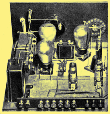
The inventor of the phonograph, Mr T A Edison, recently celebrated his eighty-first birthday, and here is seen his first instrument for the recording and reproducing of speech. The recording was carried out on tin-foil, wax being used at a later date.
Pick-Up Adjustment
The question of pick-up adjustment and volume control seems to worry a great number of people, though it is not a difficult one by any means.
In the ease of volume control, a 500 kΩ potentiometer should be placed across the pick-up and the slider of the potentiometer connected to the grid of the detector-valve of the set - assuming that you are going to use the detector as the first LF when the pick-up is employed.
This potentiometer should be well made and will give perfect volume control besides assisting in increasing the stability of the set, a quality that is sometimes lost to a greater or less degree when a pick-up is fitted.
As regards pick-up adjustment, this is a more difficult matter, though it is easy enough in the case of many pick-ups which have adjusting screws. These either operate on the armature or on the damping device, but the effect is the same - to make the pick-up more or less sensitive.
Sometimes, however, the pick-up is of a more intricate construction, such as in the case of the Woodruffe, and R I Varley, which are more difficult to adjust, or in the case of the Phonovox, BTH, Crossley Merola, etc., which have no apparent means of adjustment. In such instances it is advisable, should the pick-up go out of adjustment, to send the instrument to the makers, who will be pleased to readjust it for you.
Overloading Valves
In the ease of the R I Varley pick-up the adjusting screws are sealed, and the makers state that they prefer to have it sent back if it goes out of adjustment, adding that they take no responsibility if the seals are broken.
Before blaming the pick-up, however, make sure your set is in good order, for an overloading valve will often give the same result as a, pick-up whose armature is out of adjustment and is occasionally touching and momentarily adhering to the magnet pole-pieces.
And talking about overloaded valves, make sure that your first valve is not getting from the pick-up more than it can carry, by fitting a potentiometer volume control across the pick-up. Very often, if the pick-up is at all sensitive, an RC valve may be badly overloaded on loud record passages, and the writer prefers to use the ordinary HF valve, with an impedance of about 20 kΩ and a magnification factor between 15 and 30, as detector, if the set is to be used for pick-up work.
Also, if you would avoid instability, donbt take your pick-up leads over the loud-speaker leads, and donbt have longer pickup leads than you can possibly help. Earthing the tone-arm and sometimes the motor of the gramophone also often helps in eases of tendency to howl or squeal when the pick-up or tone-arm is touched.
The choice of needles will make a difference in the reproduction, of course, and the half-tone needle seems best suited to the majority of highly damped pick-ups. Others work better with loud-tone needles, especially the Woodruffe and R I Varley, but loud needles on highly damped pick-ups seem to cause unnecessary record wear.
Change the Needle
A little experiment with various types of needles is always worth while, and it is wise to remember that a once-used needle often acts as a miniature chisel upon the record, especially if the needle is given a half turn to 'use a fresh point', as so many people do.
Steel needles should be used for one side only, when the needle 'grinds itself in' to fit the particular record and should on no account be used again - not even on the same side.

To be continued ...
|