|
Although the push-pull system of connecting low-frequency amplifying valves is not very widely used in this country, and the difficulty of obtaining components has discouraged amateurs from experimenting with the arrangement to any great extent, the method of connection nevertheless possesses certain definite advantages.
With the advent of the moving-coil loud speaker, and the increasing appreciation of high-quality reproduction, there is among experimenters a tendency towards building more powerful amplifiers, this being evidenced by the rapid growth in popularity of the super-power valve. It is probable, therefore, that the push-pull system of amplification will receive more attention in the future, and, as there is a considerable diversity of opinion as to whether the system is worth while, it is proposed here briefly to outline its operation and advantages.
How It Works
For those who are a entirely unfamiliar with push-pull, it may be said that the arrangement is one in which two valves are connected in such a way that the incoming signals are split up and divided equally between the grids, whilst the corresponding plate currents join and add together in the following transformer.
The system differs from that in which two valves are connected in parallel, in that each grid receives only half of the signal voltage, whereas in the parallel circuit the full voltage is applied to each.

In Figs. 1A and 1B are shown simple push-pull and parallel circuits respectively, all filament connections and circuit details being omitted.
Splitting the Input
Referring to Fig. 1A, current from a detector or low-frequency amplifier passes through the primary winding of the transformer T1. This produces a voltage across the ends a and b of the secondary winding, but instead of this voltage being applied between grid and filament of one valve, it is applied between the grids of the two valves.
A lead is taken from a centre tapping of the winding to the grid battery, and thence to the low-tension negative.
Then if, for example, the voltage across the points a and b is 4 volts, the potential of each point must be 2 Volts different from that of the centre point c. One end will be positive while the other end will be negative, so that there is, in effect, a voltage on the grid of V1 of 2 Volts positive relative to its own filament, and a voltage of 2 Volts negative on the grid of V2.
In the parallel circuit shown in Fig. 1b, a difference of 4 Volts between a and b would mean that both grids would he at a potential of 4 Volts relative to their filaments, and both would be positive or negative at the same instant.
Combining the Output Currents
These examples, of course, disregard the voltage of the grid battery.
Reverting now to the push-pull circuit, the effect of two equal voltages of opposite polarity on the grids of V1 and V2 is to cause equal but opposite changes of plate current from the two valves. Thus 2 Volts positive on the grid of V1 might produce an increase of 2 milliamps in its plate current, i.e. through the portion d e of the primary winding of the transformer T2, whilst 2 volts negative on the grid of V2 would produce a decrease of 2 milliamps of the Winding f e.
Since the windings d e and f e are simply one continuous winding, all in one direction, tapped at the point e, the effect of these two changes of 2 milliamps is exactly the same as would be produced by a change of 4 milliamps flowing straight through from d to f, and a corresponding voltage is produced in the secondary winding.
In short, the plate currents have added themselves together, just as much as they did in the parallel circuit, even though each of the grids only received half the input voltage.
Power Capacity

The difference between the two systems can be seen from the characteristic curves shown in Fig. 2, in which the bottom bends have been omitted, in order to simplify the diagram.
Curve 1 is assumed to be the grid voltage-plate current characteristic of one of the valves shown in Fig. 1.
In the push-pull circuit, Fig. 1A, since the grid-input can be double, and will then double the plate current changes, the operation of the two valves can be represented by Curve 2.
In the case of the parallel connections, Fig. lB, each grid receives the full signal voltage, and so the system cannot handle any greater input than if a single valve were employed. The plate current, however, is doubled for a given grid voltage, making the slope of the characteristic twice as steep, as shown by Curve 3.
Push-Pull with Chokes
Summarising, the push-pull arrangement allows twice the input to be handled without over running, but for inputs up to half the maximum is no better than a single valve, whilst the parallel system cannot handle any greater signal strength than can a single valve, but for a given input provides twice as much plate current variation.
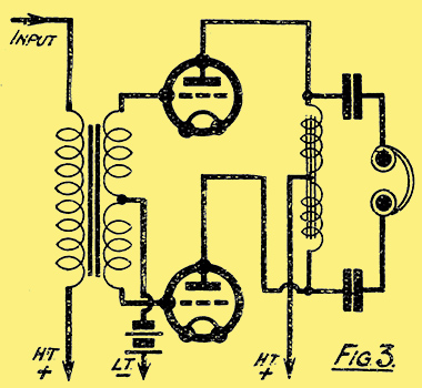
The push-pull system can also be applied to a choke-coupled output circuit, as shown in Fig. 3, the output choke consisting of two windings in series, both wound in the same direction on the same core.
There are two respects in which the push-pull arrangement offers definite advantages over the use of one super-power valve having similar characteristics, and these two may be found to outweigh the additional cost of the system now that push-pull components have become more readily available.
Freedom From Saturation
Firstly, it will be seen from Fig. 1A that although the valve output currents add up in the primary transformer winding, the DC portion from the high-tension battery divides at the point e, and flows in opposite directions through the winding, and so produces no steady magnetic field through the core. Now, it is the superimposed direct current in the primary winding of a transformer, or of an output choke, which makes it difficult to construct a high-inductance winding for use after a power valve, for the effect of the direct current is to saturate the core, and reduce the inductance very considerably, giving rise to poor amplification of low notes, and peak voltages.
Consequently, a push-pull transformer or choke, in which no direct current magnetisation occurs, will have a higher inductance than will a single winding of a similar number of turns and section of core.
Reduced Distortion
The second respect in which push-pull scores is that each valve can be overrun so as to work a little way round the bottom bend of its characteristic, without introducing appreciable distortion.
The equation to a valve characteristic provides a simple proof of this, but an actual example will probably be more convincing.
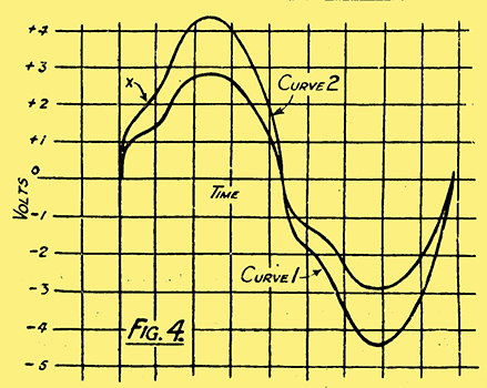
Suppose that the speech wave which is being received is as shown in Fig. 4, Curve 1, and that it is being applied to the grid of a power valve, the characteristic of which is shown in Fig. 5.

If we bias the grid of the valve at the point A, the maximum positive value of the speech wave, which is about 3 Volts, will fall just short of the zero-grid-voltage mark on the valve curve, whilst the maximum negative value (3 Volts more negative than the bias point A) will reach just to the beginning of the bottom bend, at the point C. The corresponding changes in plate current give a curve which is a replica, of that shown in Fig. 4, and no distortion is introduced.
If, now, the speech input were increased to give a grid voltage curve as shown by Curve 2, Fig. 4, the valve would have to be biased with 4.5 Volts at the point B, in order to avoid the grid becoming positive when the maximum positive voltage was received. The maximum negative voltage (4.5 Volts beyond the bias voltage), however, would now occur at the point D, which is well off the straight portion of the curve.
The resultant plate current wave can easily be plotted by determining from Fig. 5 the plate currents corresponding to a number of voltages one the curve in Fig, 4, and plotting these on a base-line divided similarly to that in Fig. 4.
For instance, the point X on Curve 2, Fig. 4, representing a positive grid swing of 2 Volts, is shown on the valve characteristic at X, which corresponds to a plate current of 4.7 milliamps.
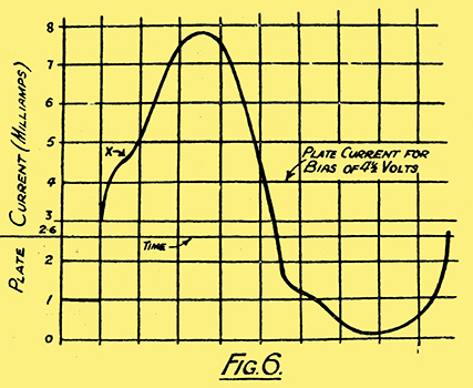
A curve plotted in this way is shown in Fig. 6, from which it will be seen that the shape of the negative half of the wave is very much changed by the bend of the characteristic.
In practice, this would mean bad distortion.
Suppose, now, that we applied the same voltage wave to a push-pull stage comprising two valves each capable of handling only half the grid swing of that represented in Fig. 5.
A Balanced Effect
Then, since each grid receives half the signal voltage, the plate current wave from each valve would be exactly similar to the distorted wave shown in Fig. 6. When one valve was giving the distorted negative half-wave, however, the other would be giving the undistorted positive half, and vice versa, as shown in Fig. 7.
Curves 1 and 2, show that the total plate current half-wave in the output transformer would be given by the sum of a distorted and undistorted half-wave.
By adding the values at any instant of the Curves 1 and 2, therefore, we can get an idea of the plate current wave-form produced by the push-pull stage. This is shown by Curve 3, Fig. 7, which will be seen to be almost an exact replica of the original voltage wave in Fig. 4.
Worth Careful Consideration
Under working conditions, of course, the valve curve would be considerably flatter than that shown in Fig. 5, but the static characteristic has been used here in order to show the effects of distortion more clearly.
It is evident from this example that, although we may replace a push-pull stage by one large valve having a similar characteristic, the former may be given a higher grid bias than the latter, and so will deal with larger inputs without serious distortion.
Finally, it may be advanced that the very extensive use of the push-pull system in America at least, merits its careful consideration by experimenters who are desirous of dealing with very large volume with a minimum of distortion.
|