|
An article that should receive the careful attention of all who intend to use, or are using these useful components.
So popular has the dull emitter valve become that it seems likely to supersede others whose brightly glowing filaments require anything up to an ampere of current to bring them to their proper working temperature. Dull emitters have been for some time in use in the Navy and they have been adopted by severed recent exploring expeditions, owing to the smallness of their current requirements.
The amateur is confronted by so large an array of low temperature valves of different design that he may have some difficulty in making a choice. It may help him a, little if I make a, brief mention of the various types that are now available.
The Three Types
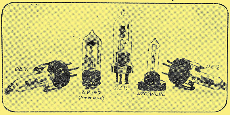
A group of typical dull emitter valves.
DEV, UV199, DER, Wecovalve & DEQ.
Dull emitters can he divided into three classes: those whose current consumption is not much less than is the case with the old type of valve, though the voltage needed is low; those in which the current consumption has been reduced to something very small whilst the voltage remains comparatively high; and, lastly, those in which both voltage and current have been brought down to very small values.
To the first class we may assign most of the earlier dull emitters designed in this country. These are such valves as the M-OV DER (1.8 Volts, 0.4 amp.), the Mullard LF ORA (1.8 Volts, 0.2 to 0.4 Amp.), and the Ediswan ARDE (1.5 to 1.8 Volts, 0.25 Amp.). None of these is really suitable for working off dry cells. All are excellent performers, and, owing to their comparatively stout filaments, they are very long lived. I had one set of DERbs in constant use for eight months, and though they have now been replaced for general work by valves which take less current, they are still as good as ever.
To the second class we may assign the M-OV DEV and DEQ (3 Volts, 0.18 amp.); the M-OV DE3, the BTH B5, the Ediswan AR06 and the Mullard DF ORA (all 2.5 to 3 Volts, 0.06 Amp). The first pair mentioned are by no means new valves since they have been on the market for considerably more than a year, though their high price has prevented them from being very widely used by amateurs.
They are first rate valves of very low capacity, giving results comparable with those of their high temperature counterparts the well known V24 and QX. Carefully used they will last for a very long time. It was a set of these which replaced the DER's mentioned previously, and they have now been in use for seven months without any changes becoming necessary. The four valves of more recent design are all obtainable at 30/- apiece. There appears to be little to choose between them, and if used with care they will do everything that the amateur requires. In the last class we have up to the present two valves only: the Wecovalve and the Cossor Wuncell, both of which are within the capacity of a single dry cell of ordinary size. These are both well made, robust little valves, very pleasant to work with.
Restoring Dull Emitters
The soundest hint that can be given for using dull emitters in general is not to over do the voltages. This applies to both anode and filament circuits. Dull emitting filaments are of two kinds. The first, which is the more common, consists of fine tungsten wire with which is blended a small proportion of thoria, a rare earth, used also for making incandescent gas mantles. On the surface of the filament is a very thin layer of thoria, whose presence enormously increases the electron emission. Should too great a voltage be applied the thoria may become volatilised, in which case it will be driven off from the tungsten, and the valve will cease to function as a dull emitter.
It can be brought back to something like its normal efficiency by the rather risky process known as "flashing". To do this one connects one of the filament pins to the positive pole of the high-tension battery, fixing to the other a piece of flex, whose free end is brought for the briefest possible instant into contact with the negative pole. This has the effect of bringing more thoria to the surface of the tungsten. The second kind of filament is made from either platinum or tungsten, with a coating of some lime compound. Excessive voltages here have the effect of breaking up the coating, though the qualities of the valve may be to some extent restored if the filament is left glowing for a time with the high tension battery switched off.
Voltage Control
Should the anode be overdone the life of the filament is likely to be a short one. If an old valve is broken up and its filament removed and measured with a micrometer, it will be found that its diameter is considerably less than it was when new, particularly at the negative end, where the emission of electrons is at its greatest. By increasing the anode voltage we throw a very great strain upon the filament since we increase the electronic emission, and there comes a time when the fine wire is so battered that it gives way.
Never use a filament voltage greater than that recommended by the makers, and be sure that there is sufficient resistance in the circuit to cut down the electromotive force of your battery. Three dry cells, when new will have a, voltage if wired in series of from 4.5 to 4.8. The ordinary 5 Ω rheostat is of no use whatever for bringing this down to meet the requirements of 3 Volt filaments and an auxiliary resistance with a maximum value of at least, 30 Ω should be provided. Fig. 1 shows how it can be inserted into the circuit.
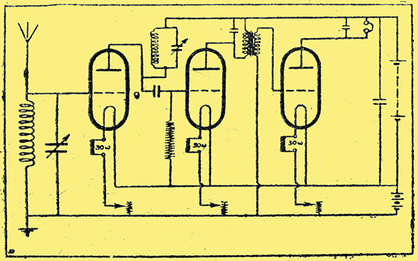
Fig, 1.
It will be seen that a resistance is provided for each valve. It would, of course, be possible to use an extra resistances for the three, as shown in Fig. 2, but if this is done it will be found that any movement of one valvebs rheostat effects also the other two. Dim one valve a little and the other two brighten; increase its brilliance and the others become duller. Such an arrangement therefore makes it extremely difficult to adjust the set properly. The next point to notice is that the plate voltage of many of these valves is extremely critical when they are used as rectifiers. With the Wecovalve, for instance, one requires something rather better than the three-volt steps provided by the ordinary high tension battery.
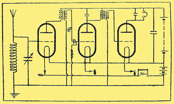
Fig. 2.
A finer adjustment may be obtained in one of two ways: either a battery of the round cells used for torches may be made up and tapped at every 1.5 Volts, or, better still, a potentiometer may be used, as shown in Fig. 3, across the three cells at the positive end of the high tension unit.
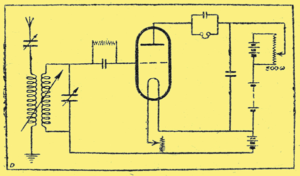
Fig. 3.
Action of Dry Cells
To obtain the best from dry cells it is essential to treat them carefully. None of them will stand a long continuous discharge. When current is being taken from a dry cell bubbles of hydrogen gas form upon the positive carbon element, setting up an increasingly high internal resistance which leads of course to a drop in the voltage.
This polarisation, as it is called, is counteracted to a great extent by the depolariser of manganese dioxide, which gives up one, of its oxygen atoms to each part of hydrogen atoms, thus dissolving the bubbles and forming water which goes to keep the cell damp. If, however; the cell is worked with a fairly heavy load for a long time the depolariser is unable to do its proper work and the cell will be injured. It is thus necessary to rest dry batteries as much as possible. Fig. 4 shows a way in which this may be done, the double-pole change-over switch enabling either of the cells to be used whilst the other is resting.
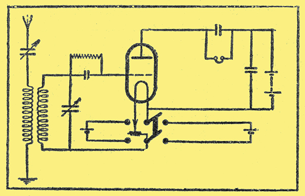
Fig. 4.
LT Accumulators
With Wecovalves and others which have a fairly high current consumption (for dull emitters, that is), it is best not to attempt to work two or more in parallel from one cell no matter how large it may be. Nor is it advisable to use such a circuit as that shown in Fig. 5, where three cells in parallel are called upon to work three valves.
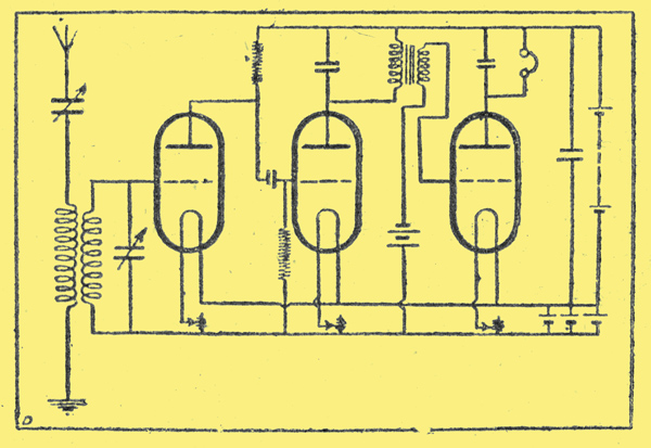
Fig. 5.
It is better to use a separate cell for each valve, as shown in Fig. 6.
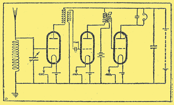
Fig 6.
If accumulators are used for heating low temperature valves the result is delightful, for onebs low-tension battery lasts an immense time with one charge. It must, however, be remembered that the plates of any accumulator, unless it is a very special kind, suffer if the battery is not charged up every three months or so. Therefore, even though it appears to be up to its full voltage, it should be sent to the charging station at regular intervals for attention.
Careful Treatment Necessary
Filament current should not be switched on suddenly; that it to say, it is not advisable to leave the rheostats at their best setting and, when the receiving apparatus is brought into use again, simply to plug-in or switch on the low-tension supply. Curious things, into which there is no space to enter here, take place in an electric circuit which is suddenly brought under full load. The result, however, is that a momentary heavy strain is set up. This is specially undesirable in the case of filaments which are particularly brittle during, the brief instant in which their temperature rises to the working point. Matters are made much worse if the high tension battery is connected up when switching on is done. In this case the full strain of emission to the plate is placed upon the filament suddenly just at its weakest moment. Therefore switch on your filaments gradually through a resistance and do not connect the high tension supply until they have been glowing for a moment.
You will have no fault to find with the performances or with the life of low temperature valves if you are careful with them. Remember that their filaments are much thinner than those of high temperature valves and handle them with corresponding care. Always mount valves in the set so that their filaments are vertical. If they are horizontal the combined influence of gravity and of static pull from the anode tend to make them sag down on to the grid. Treat your dull emitters considerately and they will serve, you well, but handle them carelessly and you will find that they are expensive luxuries.
Filament Control
As only at small amount of current flows through the dull emitter filaments, it is obvious that a small variation of current will make a large variation in electron emission. Therefore, in order to control this type of valve to the best advantage a filament resistance capable of vernier adjustment, is necessary and on no account should the same rheostat be used for several valves.
The rheostat chosen for use should also be perfect in action, as any slight irregularity in current due to poor or unequal contact in the rheostat will be greatly magnified by the valves, and so give a surprising variation in the phones, besides causing a considerable amount of unwanted noise.
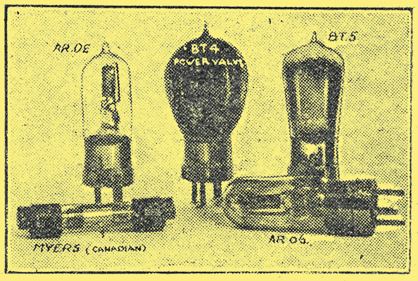
Another group of typical dull emitter valves
Myers, ARDE, B4, B5 & AR.06.
|