|
One of the problems of the listener today is to know how to keep up to date. It is easy to say relegate to the scrap-heap any set when it begins to get obsolete, but considerations of economy often decide otherwise, and it then becomes necessary to see what can be done, even if we may have to compromise a little, to effect improvements. The purpose of this article is to guide the listener and discuss valve changes which are permissible whilst giving warning of changes which might result in trouble.
There are a vast number of listeners unwilling to scrap the receiver which they know how to handle, gives them satisfactory service, and adequately meets their particular requirements. On these occasions the user feels that the introduction of one or two more modern types of valves should give the set an increased efficiency either by a saving in running costs or better performance. Perhaps also such a receiver has been prone to microphonic or ringing noises associated with the design and types of valves available at the time the set was produced, and some improvement is called for in this respect.
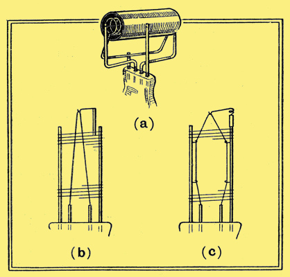
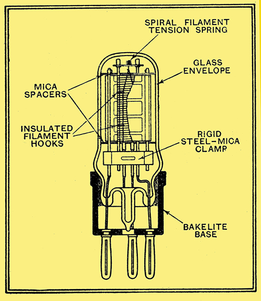
Illustrating (a) simple construction of original DER triode. The low efficiency and heavy filament enabled simple design to be used, without danger of introduction of microphony. (b) Early design of hairpin filament which led to microphonic troubles as the efficiency increased. (c) Modern design of battery valve filament, employing anchored and sprung supports to shorten length of free filament and maintain constant tension.
It is seldom practicable or possible to introduce new features in the way of components in bringing an set up to date, with the exception of the valves. Batteries, in the case of a non-mains driven receiver, are, of course, calling for constant renewal if the receiver is to be kept up to a certain standard of efficiency, but how often is the other replaceable component, namely, the valve, allowed to deteriorate before serious attention is paid to the renewal of this essential part.
Most valves give an exceedingly long working life if treated kindly, but, even so, are not everlasting, and sooner or later it is false economy to keep them in service, and the question of new valves calls for urgent attention. The problem then becomes whether to fit a valve of identical type and make to the original, or whether to attempt to use the higher working efficiencies of more modern types.
In the first place there is usually a greater flexibility in the choice of valves for a home-constructed receiver or kit set than for a manufactured receiver. This is because the set manufacturer usually designs rigidly around a given combination of valves both on account of physical size and electrical characteristics, and often for either of these reasons a departure from the types specified is dangerous or impossible. In any case it is usually good policy to refer the matter to the actual manufacturer concerned, or to the valve manufacturers, who can usually recommend a type suitable for the particular receiver in question.
In the case of the home constructed outfit or kit set it is certainly worth some consideration before re-valving, and to assist in this it may be helpful to analyse the various changes which have taken place in the design or characteristics of receiving valves during the past eight or nine years.
The principal features which affect the replacement of one type of valve by another are:
Size, type of fitting (base, pins, etc.), filament voltage, filament current, mutual conductance, grid bias, anode feed current, grid current characteristic, inter-electrode capacity, nature of characteristic - triode, tetrode, pentode, etc.
Apart from the first two considerations, which are purely physical and obvious ones, any or all of the remainder may take part in determining whether a replacement valve of another type may improve a set or render it unworkable.
Let us consider how each of these points in turn will affect performance and review the major changes in each instance over the past decade of valve manufacture.
Filament Voltage
Although now probably representing only a small minority, there are still users of battery sets who employ a 6 Volt accumulator, this being a relic of the days when 6 Volt valves were used in order to get a performance not then possible with valves of lower voltage. By the improvement of filament technique enabling a greater electron emission to be obtained from a modern 0.2 Watt filament than was possible for a 1.5 Watt filament of ten years ago, manufacturers, by common consent, have ceased the production of broadcast battery valves with filament voltages exceeding 2.0. It is, therefore, false economy to continue the use of 6 Volt battery valves with consequent heavy bulk and heavy charging costs of the accumulator, and a change to 2 Volt valves would be a good one.
Owing to the improvement in filament technique, actually a better performance can be obtained from a set of modern 2 Volt valves providing the correct types are carefully chosen.
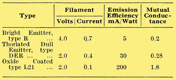
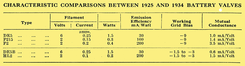
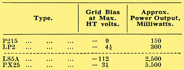
A striking example of this improvement is given in the table which compares a popular line of 6 Volt battery valves in 1925 with 2 Volt types of modern design which will replace them.
A similar argument applies to 4 Volt battery valves which can be replaced by modern 2 Volt types with a reduction in the size and charging costs of the accumulator.
In the case of mains-driven receivers the filament, or, in this case, the heater voltage is, of course, fixed by the transformer incorporated, which normally would be wound for 4 Volts, being the figure standardised in this country for AC valves.
Filament Current
Since the introduction of the oxide-coated or barium technique to replace the thoriated filament, which in its turn replaced the bright emitting filament, there has not been any marked change in the filament current taken by any particular class of battery valve. Very few sets of to-day will be employing bright emitter types of valves, but there still may be users who have valves fitted with the thoriated filament. Such valves were often exceedingly long-lived, and may even yet be giving good service. It would, however, be an economical move to replace these with modern valves, but, here again, very great care must be taken in the choice of valve and characteristics owing to the greater efficiency of these over the thoriated types. To minimise the chances of instability a modern valve of moderately low impedance and low amplification factor should be chosen and worked at a fairly low HT voltage (except in the output stage), or disappointment may result.
A striking instance of the improvement in filament current efficiency resulting from changes in filament technique is afforded by a comparison of the types shown below:
In certain sets the volume control is effected by means of a variable resistance in the filament lead. Should a valve of lower filament current replace an older type the voltage drop across this resistance will be less and the control of volume may be adversely affected. The remedy is, of course, to utilise a higher value of variable resistance.
In the case of DC mains-operated sets where the valve heaters are wired in series at a constant current it is not practicable to introduce any change in this direction owing to the constants of the heater circuit.
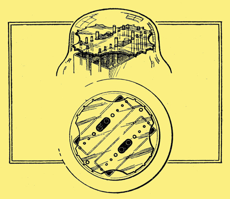
A modern type of double helical spiral heater for mains valves, to minimise hum.
With AC valves the heater current is more or less standardised and no economy is worth considering in this direction.
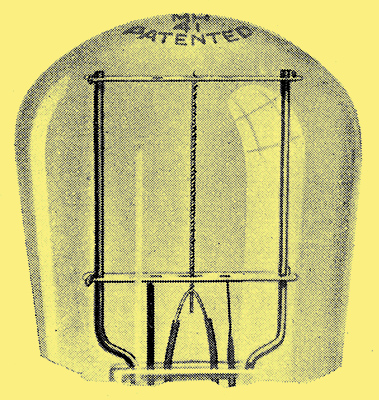
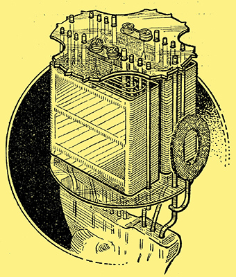
The form of bulb shaping and mica electrode support anchored to bulb shown in this sketch is adopted in many modern valves to ensure rigidity and characteristic consistency.
Perhaps the most striking change in valve characteristic over the past decade is the rapid climb in mutual conductance which applies to every class of valve and is directly the result of improved emission efficiencies. This, while affording a means to greatly improve efficiency in performance when treated with discrimination, represents also the biggest difficulty in the way of introduction of modern improved valves to replace valves of older types. The reason is, of course, that the improvement in mutual conductance will probably result in an increased overall gain per stage and unless the receiver is designed with adequate screening and decoupling of the various stages this increased gain is reflected in feedback, giving rise to uncontrollable oscillation either of radio or audio frequency.
Great care must, therefore, be observed in the choice of modern valves, and in the case of most earlier set designs it is not practicable to take full advantage of the increased amplification that they offer.
Most valve makers, however, have a range of valves having modern characteristics in every other respect but so designed as to give the advantages of present-day technique in an older type set without introducing instability. This question is best considered under two heads:
- Valves for radio frequency, i.e., HF and detector stages
- Valves for audio frequency, i.e., LF and power stages.
On the radio-frequency side the effect of increased mutual conductance must be considered in conjunction with the value of anode-grid capacity. To take as an example a triode used as an HF amplifier (common practice until recent years) any attempt to introduce a valve in which the product of factors representing mutual conductance and capacity is increased will undoubtedly lead to instability. In a triode valve this state of affairs cannot be avoided, and hence with HF amplifiers using triodes (either aperiodic or neutralised tuned circuits) any improvement in the mutual conductance of the valve types hitherto used is impracticable.
In the case of the detector stage, the effect of any increase in the mutual conductance &mult; capacity factor will have its effect on the reaction circuit - usually an important section of older type sets, and if ganged circuits are used some retrimming of the condensers will probably be necessary.
Illustrating a modern development in battery valve design the HL2/K triode, primarily intended to reduce microphony, increase uniformity, and economise in space. The type is suitable as detector in practically all battery sets using triodes.
Renewal of the detector valve is, however, a move with strong recommendation and very often results in markedly improved range-getting properties. A valve of medium impedance is generally preferable, and the increase in sensitivity often allows a reduction in HT voltage, with resulting saving in HT current.
With screen grid valves, the problem of attempting to improve results with a modern valve is more complicated as so much depends on the lay-out and degree of screening provided in the set. It is usually impracticable to attempt the introduction of a valve having more than 1.5 times the mutual conductance of the original, unless the screening is very complete, but modern design screen grid valves with a restricted gain can be used, such valves often showing a reduction in HT current at the same time.
The following summary of advice may be helpful
Detector
Use medium impedance valve.
Reduce HT volts if reaction too fierce.
Reduce value of grid leak if reaction "Ploppy"
HF Amplifier Triode
Use valve of similar mutual conductance as in type originally specified.
HF Amplifier Screen Grid. One stage
A higher mutual conductance may be beneficial. Decrease screen volts if instability experienced.
HF Amplifier Screen Grid. Two or more stages
Use valve of similar mutual conductance unless otherwise recommended by makers.
A material improvement can often be effected in a single-stage HF amplifier, but the advice of the manufacturers should be obtained before re-valving a multi-stage HF amplifier.
It is on the audio-frequency side that there is special scope for improving old sets by substituting new valves, for advantage can then most frequently be taken of improved mutual conductance. This improvement takes one of two forms, either higher amplification factor or lower impedance. The former case results in a shorter grid base for a given HT voltage, thus necessitating a reduction of the applied negative grid bias. Having revised the bias, the effect of such a change is to increase the sensitivity to weak signals, but increased control of the stronger signals becomes necessary to avoid over-modulation and distortion.
If a valve of higher mutual conductance is chosen on account of its lower impedance value, the effect in an output stage is to increase the potential, power output.
In some cases an audible improvement in this may be accomplished without modification of the circuit, but it is preferable to adjust the output load resistance to suit the optimum figure for the valve by means of a suitable transformer or choke.
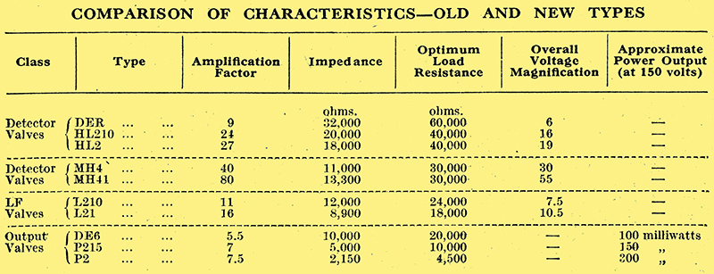
Very often - particularly in receivers of older design the decoupling provided is inadequate to prevent feed-back when the stage gain is increased, and in many cases no decoupling at all was necessary with the older low-efficiency valves. Insufficient or badly arranged decoupling results in audio-frequency oscillation, or 'motor-boating', and this factor should be taken into consideration sin making any increase to the amplification by the introduction of new valves. The table below gives a comparison of maximum voltage amplification and power output, showing the differences in, these respects between old type and modern valves of comparable classes.
In replacing a valve of one type with one of another it seldom happens that a simple interchange of valves can be effected without any modification to supply voltages, and particularly is this the case with LF amplifying or power valves. The non-technical user is liable to be misled by advertisements extolling increased amplification by the introduction of this and that new valve and .to forget that any triode valve to give greater voltage amplification, or higher 'amplification factor', can only do so by reason of a closer grid control. (Increased amplification in a screen-grid tetrode or pentode valve is mainly a function of the mutual conductance, and in such cases 'amplification factor' has little or no practical meaning.) Higher 'amplification factor' involves a shorter grid base, and hence the replacement of an LF or power triode by another of a higher factor means a reduction in the grid bias, or anode, current distortion will result.
Should the replacement of a screen-grid HF valve be under consideration; the introduction of a variable-μ type may be well worth while as permitting an easy and efficient means of volume control. The grid-bias volume control method may be applied in addition to any other method already in use with the original valve, and is likely to produce a valuable improvement in these days of 'more and higher-powered' stations.
In the case of battery-operated sets the HT current feed is one of the most important considerations, and by a careful study of valve characteristics it is often possible to economise in the current drain compatible with a certain standard of amplification in the HF stages. Here, again, the introduction of a variable-μ valve is of benefit in that the HT current taken is very small when biased to such a negative grid voltage as will reduce the volume sufficiently for local-station reception, and an economy is effected.
The reverse state of affairs exists at the low-frequency end of the set, where any improvement designed to benefit power output will increase the anode-feed current and must be considered in conjunction with the nature of the HT - whether battery or mains-rectifier equipment - as any such increase in power must necessarily involve either larger-capacity batteries or a more generous rectifier output.
Grid-Current Characteristics
Under the heading of grid-current characteristics should be included the forward and reverse currents taken by the control grid and also the currents taken by any other grid, such as the 'screen' grid of a tetrode.
Fortunately, with modern hard valves correctly used, the variation in reverse grid current which indicates softness of vacuum need not seriously enter into the picture, and seldom does the question of positive grid current affect the position as regards replacement valves. It should, however, be noted that with large power valves a total resistance in the grid circuit of more than 250,000Ω is not recommended, this resistance to include grid leak, any HF blocking, decoupling, etc. The screen-grid current in tetrodes and pentodes is important as its value will affect the actual voltage applied to the screen grid. It might thus be quite feasible to obtain poorer results from a replacement valve even though of higher efficiency, simply because its screen current being higher than that of the original valve, a lower actual screen voltage is obtained, thus restricting the input and magnification. The remedy is to adjust the values of resistance in the screen grid feed circuit to those recommended by the makers.
Inter-electrode capacity is an exceedingly important characteristic which has marked effects on receiver performance, more particularly in receivers incorporating ganged circuits. When substituting valves in sets in which the tuned circuits are ganged, therefore, it is essential that some attention should be paid to the trimming capacitors if the anticipated improvement is to be realised. Different types of valve vary considerably in capacity - from about 0.002 pF to 0.01 pF for the anode-grid capacity in screen grid valves, and from 3 pF to over 14 pF for triodes. The high values present with certain power triodes call for precautions in the grid circuit to prevent distortion caused by spurious oscillation. Introduction of a series resistance in the grid-filament circuit, or across the inter-valve transformer secondary, is helpful in enabling full advantage to be taken of improved valves.
Pentodes
The VMP4K, an HF screen pentode with inter-electrode capacity as low as the best screen-grid tetrode.
It is a common belief that the introduction of an HF pentode in place of a screen grid tetrode will result in considerable benefit in HF gain, and in certain cases this may be so. Such a step, however, should not be taken without due consideration for other constants in the circuit.
For instance, it may be that the anode-grid capacity of the pentode in combination with a high value of mutual conductance will introduce such feed-back in a circuit as to render the whole HF amplifier unstable. Some HF pentode valves show an anode-grid capacity very much in excess of the screen grid tetrodes, and thus necessitate the use of tapped tuning coils if stability is to be maintained and selectivity not spoiled. Later types, an example of which is the VMP4K type, have an inter-electrode capacity as low as a screen grid tetrode, and these valves can usually be employed in place of tetrodes with improved gain providing suitable tuning coils of high dynamic impedance are used to take advantage of the pentode characteristic.
Another point to bear in mind is, of course, the difference in the pin arrangement ; most HF pentodes bearing a seven pin base which enables the metallic coating to be earthed, and thus a change is necessitated in the type of valve holder and the wiring of this.
A third point to bear in mind is that the resistance network suitable for an original screen grid valve in a set is not necessarily applicable to the HF pentode, and the manufacturers instructions should be carefully followed in such cases.
The introduction of an HF pentode to the detector stage is also often worth consideration as tending to improve both the selectivity and the sensitivity of the receiver.
The Output Stage
Many users wishing to increase the sensitivity of a receiver are desirous of changing the output valve, if a triode, for one of the pentode class. While this modification will undoubtedly result in an increase in magnification, certain precautions are necessary if quality is to be maintained.
For instance, it is never advisable to adopt such a change if the LF amplifier employs an intermediate stage of amplification between the output and the detector. The use of pentodes should be restricted to sets with a single stage of LF only. Secondly, it is extremely important to make certain that the correct matching is employed between the pentode and loud speaker by means of a suitable transformer. In the third place a filter to prevent undue amplification of the higher frequencies is essential, and this usually takes the form of a capacitor and resistance in series across either the output transformer primary or the grid filament circuit of the pentode.
When employing pentodes it is also advisable to use as high a value of HT voltage as permissible, as the quality of reproduction deteriorates with a falling voltage on the pentode to a greater extent than is noticeable with a triode.
The QP21, a double pentode, which with proper precautions, can be used for the final stage as a class B output.
In addition to the simple changes of valves which have been outlined above, together with the precautions to be observed before any such change can be adopted, there are, of course, more complicated modifications which can be attempted by the more experienced reader. Thus it is sometimes possible in battery sets to introduce a Class B output stage in place of that hitherto employed. The double pentode of the QP21 type facilitates this owing to the fact that no driver stage is required, and all that is necessary is to modify the output valve circuit and introduce the correct push-pull transformers.
It need hardly be said that in mains driven sets no such modification of the output stage is desirable unless the whole rectifier circuit is taken into consideration at the same time.
In considering the re-valving of an AC mains set it is important that the rectifier valve should not be neglected. This valve is the source of power to the set, and is normally operating under even more severe conditions than any of the amplifying valves. A good plan, therefore, is to see that the rectifier is replaced at regular intervals, and in this case there need be no hesitation in utilising the same class of valve again - here it is helpful that rectifiers have fortunately been more or less standardised between various valve manufacturers.
Space does not permit of further discussion on the mechanical developments which have taken place in valves, but modifications in mechanical technique over the past few years would alone justify the re-valving of an old-type receiver by a reduction in the chances of microphonic noise and background interference, and by introducing a general improvement in robustness and reliability to the whole set.
|