|

The author was curious about this single ended amplifier from Douk Audio and looking through the ebay adverts came across a listing where Garry Hicks was looking for help with construction. Here is the construction process.

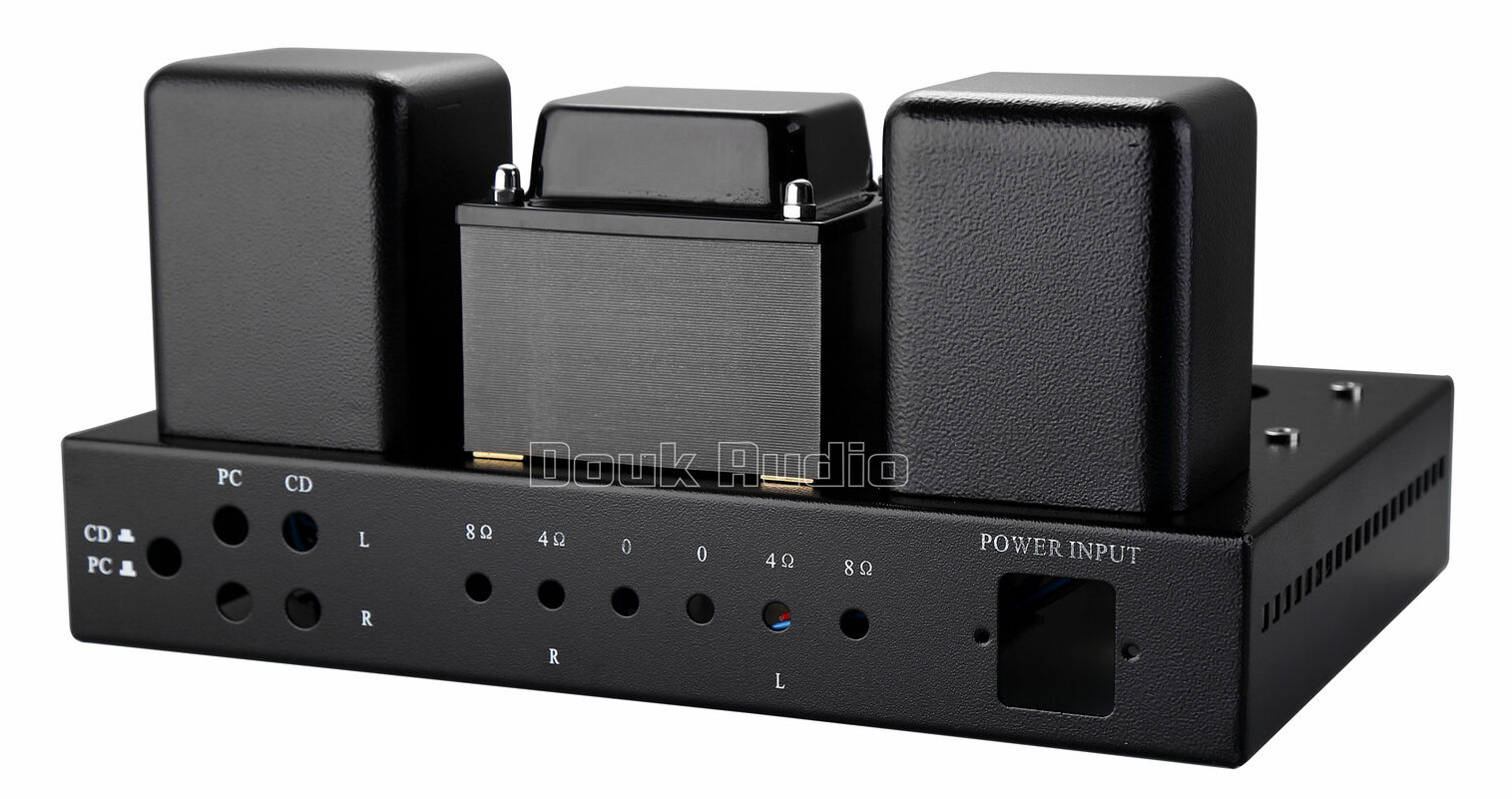
The rear of the chassis. The wound components are ready fitted.
The main chassis has a pleasing hammer finish and was held in place within the double box by foam end cheeks.

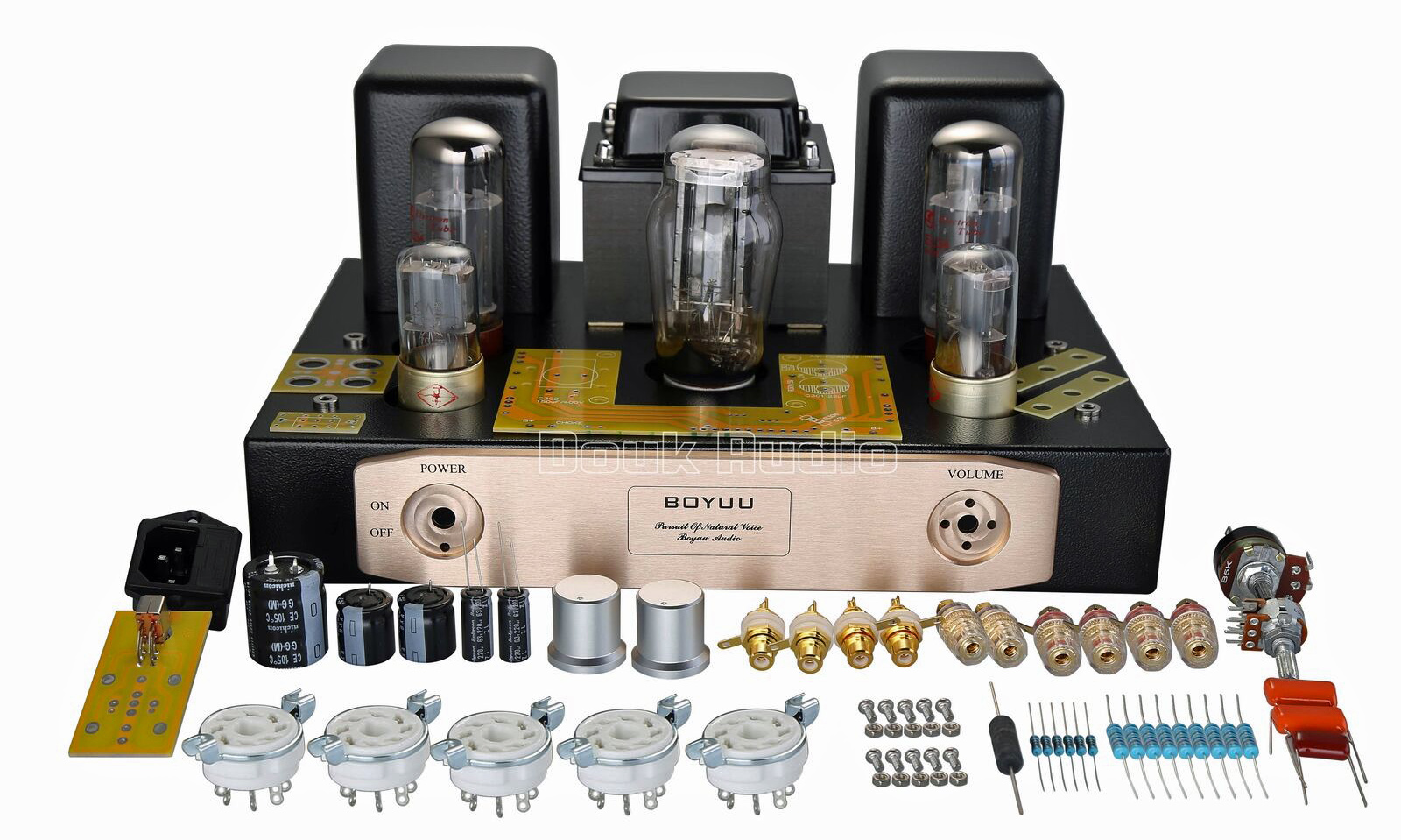
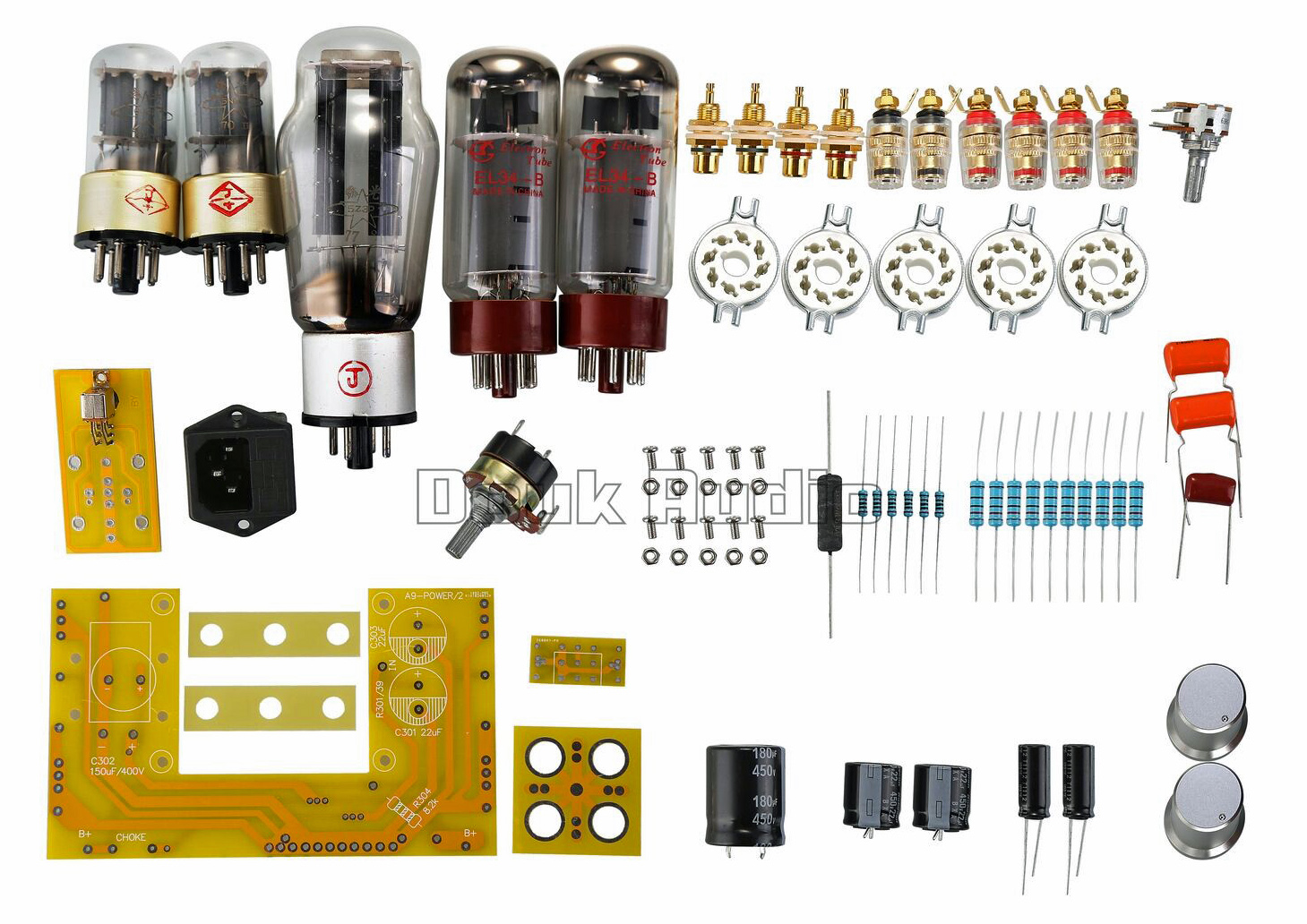
All of the supplied components.

The components sitting on the base cover. Bottom left is the input selector board.
The components were packed in sealed bags. Compression washers are supplied for the output connectors. The valve holders are ceramic. The nuts and bolts for the valve holders do not have compression washers but the retaining rings sit proud of the chassis and thus act to keep the nuts under tension. The rectifier valve holder is mounted on a ventilated metal plate with the locating spigot facing to the front.
The valves were carefully packed with a foam sheet wrapped around the five plain white boxes.

The supplied documentation consisted of a single A4 sheet giving the circuit diagram and the transformer wire colours. The mains transformer primary wire colours in the supplied unit are orange and blue. The mains transformer does not have an electrostatic screen and no HT fuse is indicated or supplied.

The circuit diagram and transformer wiring diagrams.
The initial impression is that the documentation is inadequate. After much pondering and placing the main board on the chassis pillars the correct orientation becomes clear but this amplifier would not be a constructor's initial project.

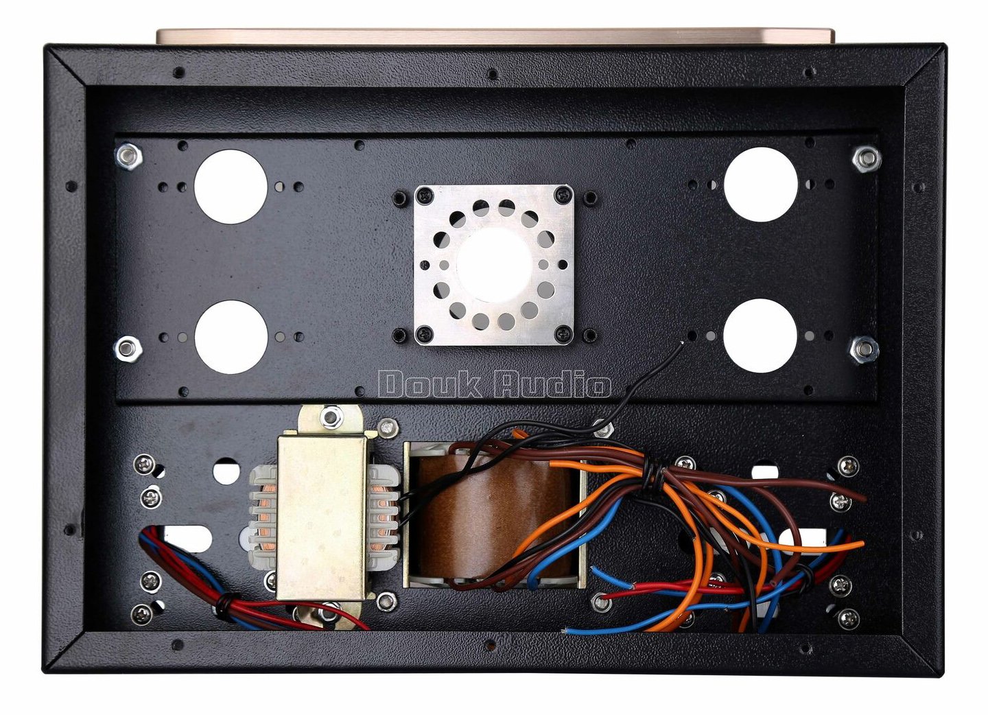
The underside of the chassis. The primary winding leads are blue and orange.
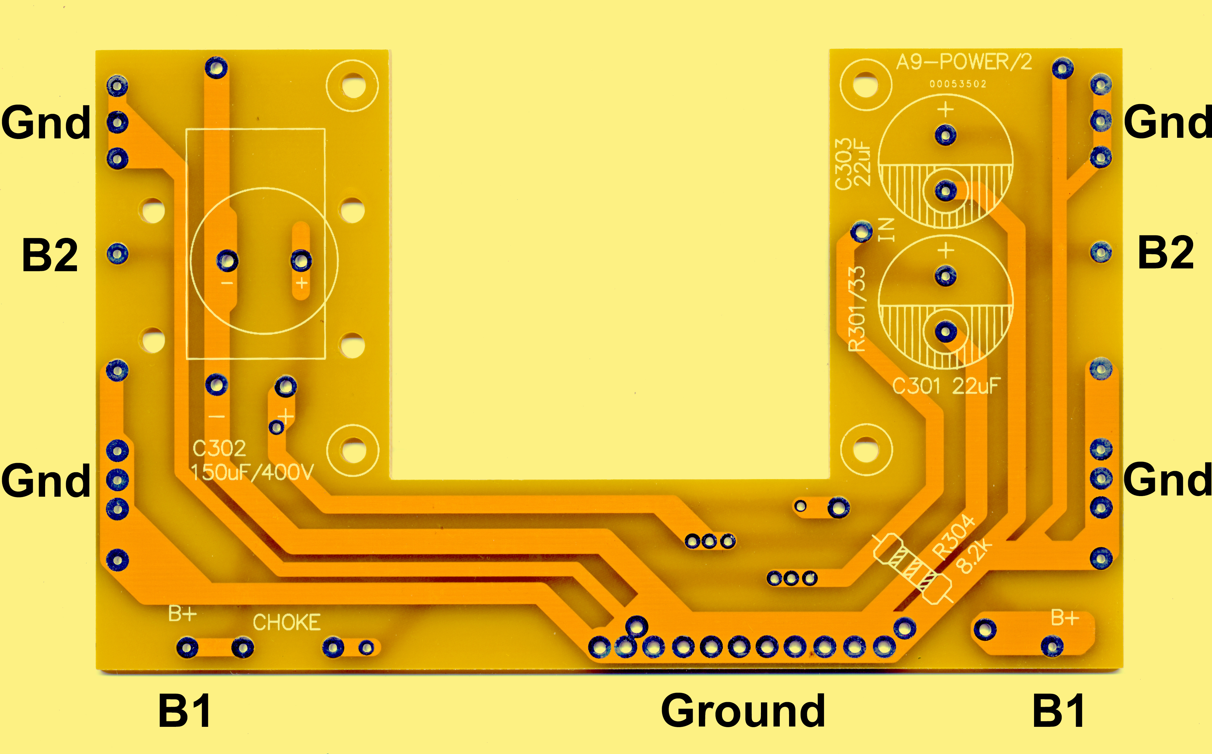
The main circuit board is for the power supply. The lettering on the board is skimpy. Below is a picture of the board with additional lettering. The amplifier components are designed to connect between this main board and the individual valve holders.

Power supply circuit board.
The power supply circuit has a current limiting resistor of 33 Ω between the rectifier cathode and the reservoir capacitor. This keeps the pulse current to the reservoir capacitor within the rectifier ratings. The circuit specifies a 22 μF capacitor, the kit has 33 μF at 400 Volts. The main smoothing consists of the choke feeding the main smoothing capacitor. The smoothing capacitor supplied is 220 μF 400 Volts. The circuit shows 150 μF at 450 Volts. I would like to see capacitors with working voltages of 450 or 600 as 400 Volts is a small margin of safety. The additional smoothing for the voltage amplifier stages is a 33 μF 400 Volt capacitor fed by an 8.2 kΩ resistor from the main smoothing capacitor. This second smoothing capacitor is also an upgrade from that specified on the circuit diagram.

Circuit of the power supply.
The main amplifier circuit has the two triodes of the 6N9P connected in parallel. For a Class A amplifier where no grid current is drawn by the output valve a single triode would have been adequate. With limited numbers of valve Types being made the octal based valve adds to the aesthetic of the amplifier. The EL34-B output valve stage has local negative feedback to the screen from the output transformer. No overall negative feedback is applied to the amplifier.

Circuit of one channel.
Construction.
The mains input connector fixes to the chassis with two black machine screws. Nuts are not needed as the chassis holes are tapped. Very little hook-up wire is supplied with the kit and additionally small diameter sleeving is supplied for the mains wires to the on/off switch. The switch was wired with the wires twisted together and carried in sleeving.
Without removing the sub chassis the front valve holders are tricky to install. Patience, the right screwdriver on top and small pliers on the nut below are required. It is easier to partly fit the first bolt and nut, insert the holder and retaining ring and slightly tighten the bolt. The second nut needs to be held while the bolt is turned to capture the nut. Then it is simple to tighten both sides evenly. The EL34-B valve holders sit in a larger diameter hole in the main chassis and are no problem to install.
The valve heaters are wired next. The heater wire needs to be twisted together to minimise the external magnetic field and placed as close to the chassis as possible. The author used cable ties and in places hot melt adhesive to hold the heater wires.
After wiring the AC wires it is sensible to check that the correct voltages appear as expected. A low voltage AC source is used a heater transformer would provide mains isolation. The author used a Variac set to 50 Volts on the mains terminal. The Variac is not an isolating transformer - be careful. The voltages were measured from each of the outputs and then multiplied by 4.4 to give the actual off-load voltage from the amplifier mains transformer.

The AC wiring almost complete.
The speaker terminals are fitted next. Check that the three thinner wires are the output. With the filter choke pre-fitted the fitting of the terminal behind the choke is difficult. Firstly solder the output transformer wire to the connector. With the terminal through the chassis hole the fibre-glass plate is fitted and the second part of the feed-through insulator pushed through the plate and chassis hole. Tipping the chassis backwards so that the terminal is resting on a soft pad allows the connector and wire to be added to the screw thread. Gently place the compression ring on the thread and finally the nut. The speaker wire hole in the outside of the terminal is used with a thin screwdriver, or similar, to hold the terminal. The second hand holds the connector to stop it rotating whilst the third hand uses the instrument spanner to tighten the nut. With care one hand can both hold the screwdriver and the pliers holding the connector. The other five terminals together take less time than the first.

Output connector spacers.
The phono input sockets are next fitted. The input selector board solders directly to the centre solder buckets so the earth connection has to be made first and a wire left to connect to the selector board. With the phono sockets loosely in place the four earth connectors can be set to form a single point in the centre of the four sockets. Solder the four earth connections together and add the earth wire. The four sockets can then be tightened without the connecting rings rotating.

The alternative is to use the PCB supplied rather than joining the tags together.

Input connector earth board.
The kit is supplied with a length of screened cable. This goes between the input selector and the volume control. As the signal conductors are fragile it was decided to solder the wire to the input selector board and then use a cable tie around the board to hold the wire in place.
The input sockets ready for fitting the selector board.
Fit the earth wire to the selector board and solder the board to the phono sockets. With this complete the volume control can be connected.

Small circuit board. The prominent track is the ground connection.
The small PCB fits to the potentiometer. With the connections pointing upwards and the spindle facing you the input is on the left and the ground pins are on the right. Place the board with the main tracks side up and the two right side pot pins are connected to the central ground track.
The input wire is soldered to the potentiometer board, left right and ground. On the output side (wiper contacts) screened cable is soldered to ground and signal pins. At the valve end only the signal connector is connected, the screen acts only as a screen. This is part of the way to avoid ground loops.
The reservoir and smoothing capacitors are fitted to the main board and then the board can be fitted to the support pillars. The rectifier plate is unscrewed as the wires pass over the main board. The board is screwed down with the main ground connections facing the HT transformer. Refit the rectifier plate. The contact pads for the choke will now be close to the choke. Fit the choke wires. The Output transformer red leads go the the main HT pads (printed as B+ on the PCB).
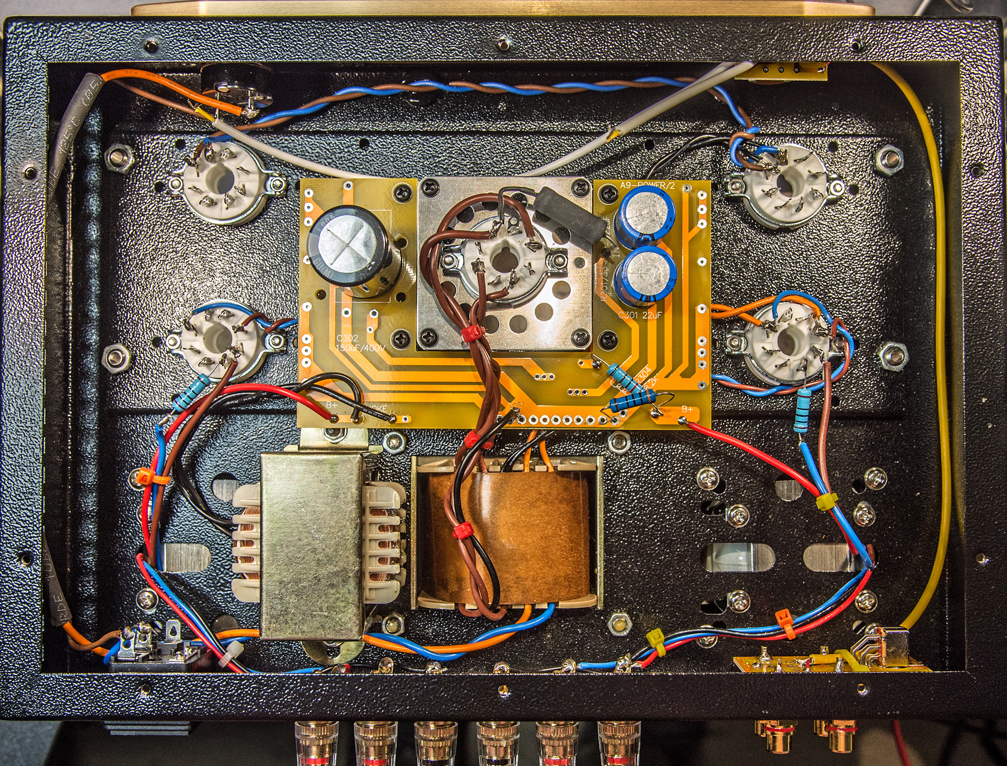
The author tested the power supply by slowly bringing up the voltage on the Variac to 220 Volts. As the rectifier heated up the voltage on the main capacitors reached 400 Volts - their maximum voltage. The power was cut and the capacitor voltage slowly decayed indicating that there were no HT shorts. The resistor across the power supply in the image below was to discharge the capacitors after initial testing. Hands were kept free until the HT had dissipated and the Variac disconnected.

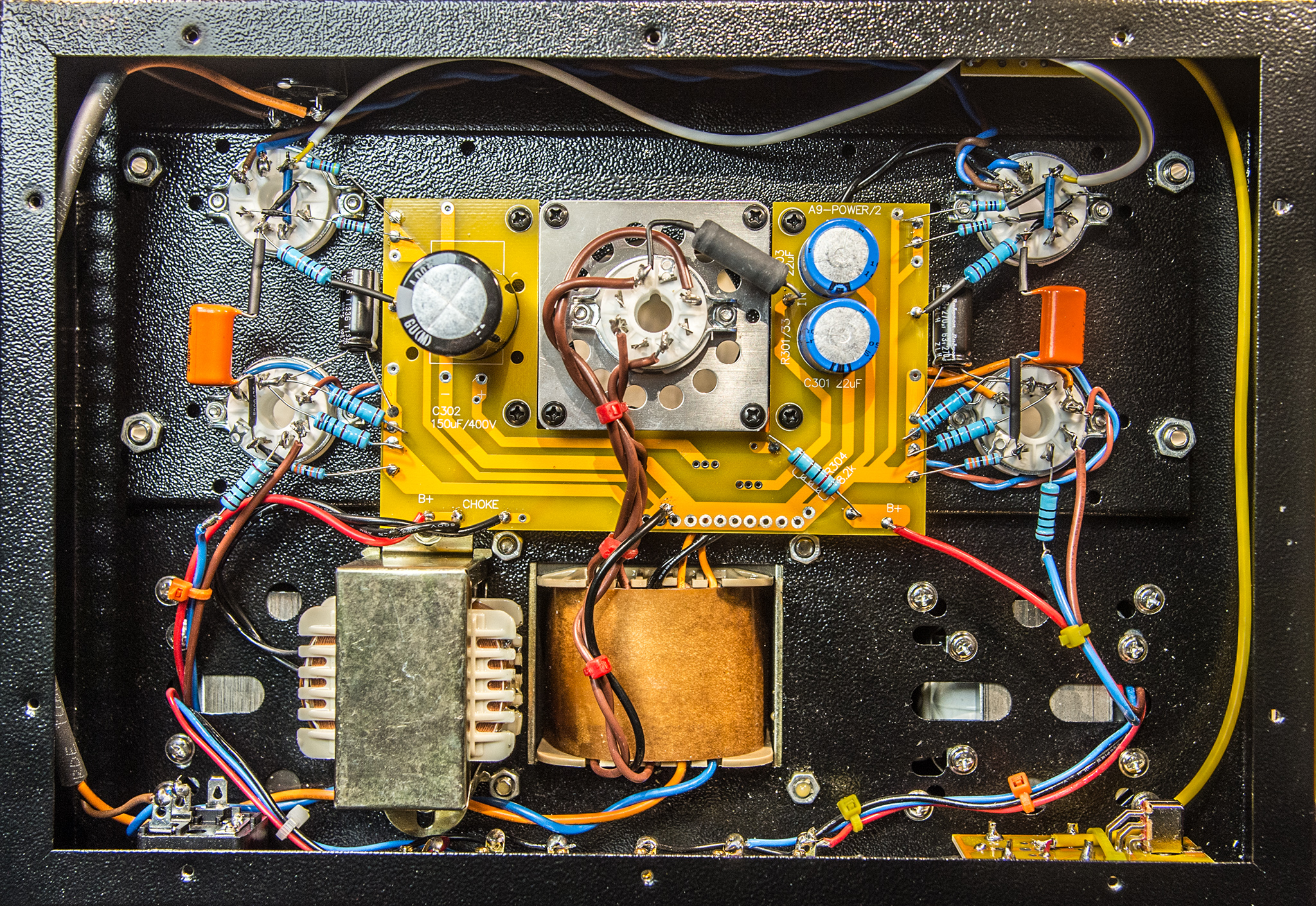
The start of adding the small components.
The small components mainly fit between the main board solder pads and the valve bases. The connections are not difficult and if taken slowly this is a most enjoyable part of the process. The input double triode is wired in parallel and so connections cross over at the centre of the valve holder. Heat shrink sleeving is supplied and provides the requisite insulation. The author started with the EL34 cathode circuits followed by the control grid resistor. The triode sections do not have cathode bypass capacitors and so it is just a case of putting the correct resistors between the valve holder and the main board. The final components are the coupling capacitors. The leads are of sufficient length to span between the valve holders. With heat shrink sleeving to insulate the wires.
The earth terminal on the mains connector is taken to the input board. The input board is connected to the ground strip on the main circuit board. This is the only ground connection from the input.
When complete the wiring is then double checked against the circuit diagram. The author checked first functionally i.e. cathode, grid, anode etc. The second check was via the valve holder pins i.e. pin 1, 2, 3 etc. back to the circuit diagram. Double checking is far better than letting the smoke out of the resistors.
The penultimate job is to attach the solid aluminium knobs. The grub screw tightens with a small Allen key (not supplied). Finally plug in the valves and attach the speakers and input source.

The completed amplifier before connecting the earth wires.
Testing
With 220 Volts AC on the input the working HT rail was at 297 Volts, this rose to 342 when the AC input was increased to 245 Volts. The 6.3 Volt AC to the double triodes was at 5.76 Volts at 220 Volts, 6.05 Volts at 230 Volts and 6.31 Volts at 240 Volts. At 245 Volts AC input the heater voltage rose to 6.43 Volts - still within tolerance.
The rectifier valve did not heat immediately. The valve has to be wiggled in the socket to finds a spot where the heater makes contact. The 5.0 Volts AC to the valve holder was not an issue. However, testing the rectifier on a bench power supply initially showed no current being drawn. Clearly a contact issue with the rectifier. Subsequently the rectifier failed. Replacing it with a GZ34 brought the amplifier to life, proving it was not the valve holder at fault. Not having a spare 5Z3P it was worth trying to fix the 5Z3P. As the most likely fault was the contact between the base wire and the pin, the heater pins were re-soldered allowing sufficient time for capillary action to draw the new solder down into the pin. Success!
The amplifier was given a listening test on the bench, Tchaikovsky's Capriccio Italien is the author's preferred initial test. At a reasonable volume the sound from a pair of Mission Bookshelf speakers was excellent. Here it must be said the author is approaching 70 and has high frequency hearing loss - not an ideal standard listener. Transferring the amplifier to the main listening room and connecting it to the Danish Jamo Satellites and sub-woofer was the next part of the subjective test. The amplifier performed well and could easily replace the existing amplifier with advantage.
Back on the bench, the right hand channel speaker was next replaced by a 4 Ω resistor. The signal generator set to 1 kHz and the output adjusted to 1.0 Watts. The oscilloscope trace of the output showed some distortion. The second harmonic from the signal generator was down 44 dB on the fundamental but measured at the output the second harmonic was only 23 dB down. The amplifier has cathode bias and that is not really the correct way to test an amplifier with a sine wave input. Additionally a resistor load on a SE amplifier will emphasise the second harmonic. No third harmonic was seen. As low level even harmonics are pleasing to the ear the amplifier performs the desired function of producing a 'warm' valve sound.
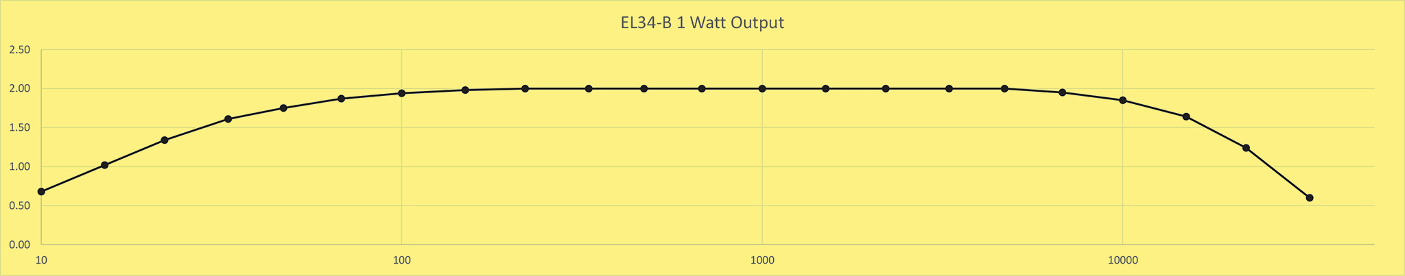
With a constant 1 kHz sine wave voltage from the high impedance output of the function generator, the output voltage was recorded for various frequencies. The E6 resistor sequence numbers (10, 15, 22, 33, 47, 68) were used for a sensibly even interval on the log X axis of the graph.

Frequency response at 1 Watt output.
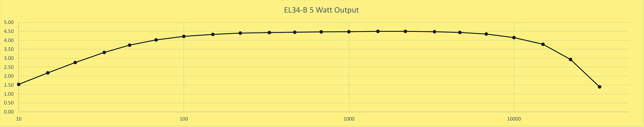
The input voltage for full output is given as 750 mV. Setting up for the next test at 5 Watts output required an input of 695 mV for the required 4.47 Volts across the load resistor. Raising the 1 kHZ sine wave to 750 mV RMS produced an output voltage of 4.72 Volts equivalent to 5.5 Watts. The EL34-B has a 500 Ω cathode resistor that develops 24 Volts. Thus the cathode current is 48 mA making the DC input to the output stage around 15 Watts. The EL34 data-sheet shows that 6 Watts is possible with a higher anode voltage. The EL34-B is thus run conservatively. At full volume it is too loud in a domestic setting and so is perfectly adequate. However, the advertised power of 12 Watts per channel is below the DC input and certainly not an accurate output figure.

Frequency response at 5 Watt output. The 3 dB power points are roughly at 33 Hz and 22 kHz.
Conclusion
If you do not measure this amplifier but just use it to play music you will be delighted. The second harmonic distortion gives a pleasing sound and the use of the two triode sections in parallel produces a roll-off at the higher frequencies due to the Miller capacitance.
Good value for money and a pleasant build experience.

The completed amplifier.
|