|
This was presented as Suggested Circuit 65.
One of the greatest difficulties experienced in the design of sensitive audio amplifiers is the necessity of reducing hum pick-up to negligible proportions. This trouble shows itself at its worst in the input stage of the amplifier, and it is at this point that most care has to be taken in design and during construction.
Normally, hum pick-up in the input stage of an amplifier can be reduced by a combination of several well established techniques. These include the magnetic shielding of inductive input components such as microphone transformers, etc.; the filtering of HT supplies; and the use of efficient electrostatic screening. However, although these steps can considerably ease hum difficulties there still remains one potential source of trouble, this being hum pick-up from the heater supply. The most sensitive point of a conventional audio amplifier appears at the grid of the input valve, this being normally connected to chassis and, thence, its cathode, via a relatively high value of impedance. Thus, whilst it is simple to keep the cathode of the input valve at chassis potential so far as hum voltages are concerned, it is extremely difficult to similarly treat the input grid and its wiring. In consequence, hum may quite easily be picked up by the input grid wiring due to stray couplings to the heater wiring. Even with modern low-hum pentodes the possibility of hum pick-up cannot be entirely rejected, and it is often found that amplifiers employing these valves still rely on such devices as humdingers to reduce hum to the lowest practicable level. As readers who have had experience of amplifier work may be aware, humdingers and similar devices are not always efficacious.
It follows from the above that, although it is possible to almost completely eradicate hum from the input stage of an audio amplifier by means of screening and HT filtering, some pick-up must almost always exist due to the presence of AC on the heater. Attempts have been made in the past to supply the heater of the input valve with DC, this being usually obtained by rectification of AC from the mains supply. Unfortunately, the heavy filtering required for such circuit arrangements, combined with their expense and relative inefficiency, render them unattractive. A quite different approach, and one which has been relatively unexplored to date, is the process of heating the first valve with an RF voltage. At first sight, this might also appear unattractive because of the possible difficulties of obtaining the power required economically, both with regard to current consumption and cost of components. However, due to the recent issue by a manufacturer of an RF transformer designed especially for this purpose, it is now possible to heat the input valve of an amplifier with RF current not only reliably but cheaply as well. The component concerned is the transformer type SSO manufactured by the Teletron Co., and it has additional applications which will be covered later on in this article. This monthbs article is concerned with practical arrangements employing the new transformer.
The Circuit
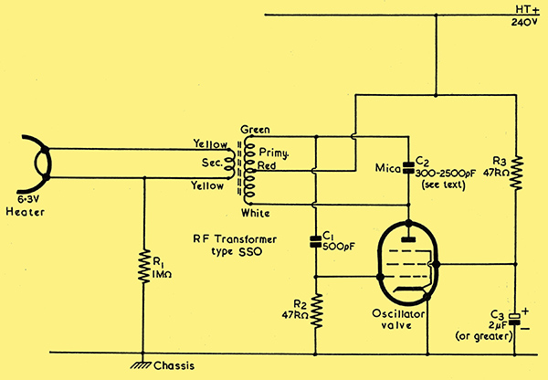
Fig 1.
The basic circuit in which the Teletron transformer may be employed is illustrated in Fig. 1. In this diagram it will be seen that the transformer consists essentially of a tuned primary coil connected in a Hartley oscillator circuit, its secondary being connected directly to the heater of the valve it is intended to drive. The oscillator valve coupled to the primary of the transformer can consist of any output pentode or tetrode capable of developing 2.5 Watts or more at 240 Volts anode voltage. Such valves as the 6V6, 6BW6, etc., fall comfortably within this category. The circuit of Fig. 1 is fully practical and can be employed as it stands.
The load, which may be imposed on the secondary of the transformer of Fig. 1, can consist of the heater, or heaters, of any valve or valves whose total current consumption is 0.3 Amp or less at 6.3 volts. Thus, a single valve consuming 0.3 amp at 6.3 Volts (such as the 6F5), could be driven by the transformer; or either one or two valves consuming 0.15 Amp at 6.3 Volts (such as the 6BR7), could be similarly driven. Assuming a fixed HT potential, the regulation of the circuit is such that the secondary voltage remains sensibly constant for current consumptions from 0.1 to 0.3 Amp. Also, due to the fact that the output heater voltage is supplied at a low impedance, values of capacity up to 0.01 μF may be connected across the secondary without altering the heater voltage obtained. There would normally, of course, be no necessity to connect a capacitor across the secondary, but this point is of importance as it ensures that no losses would be given by feeding the secondary voltage through screened cable, with its attendant capacities, should this be desired.
The efficiency of the circuit of Fig. 1 is surprisingly high. At an HT voltage of 240, and employing a 6V6 to drive the transformer, the total anode and screen grid current of the oscillator is only 14 mA for a secondary current of 0.15 amp, and 16 mA for a secondary current of 0.3 amp. Thus the additional HT loading presented by the oscillator to a conventional amplifier power pack is small. Also, the additional heater loading of the oscillator valve on the mains transformer would normally be only slightly greater than that of the valve heated by RF, which is not now connected to the mains transformer at all.
The arrangement shown in Fig. 1 does not, incidentally, incur the use of close tolerance components; 20% resistors and capacitors are perfectly adequate. In experiments carried out by the writer, empirical component variations confirmed this point.
Regulation
The regulation of the secondary voltage of the transformer depends mainly upon the regulation of the HT supply connected to the oscillator valve. In Fig. 1, the peak voltage of the RF appearing between the HT tap into the transformer primary and the anode of the oscillator tends to approach the HT voltage itself. In consequence, the secondary voltage of the transformer is directly proportional to that of the HT supply over a large range of values on either side of 6.3 volts. The transformer is designed to operate with an HT voltage of 240, whereupon the output voltage is at the rated 6.3. HT voltages of 228 and 252 correspond to secondary voltages of approximately 6.0 and 6.6 respectively. No great demands, therefore, are made upon the regulation of the HT supply. Due to the simple relationship existing between HT and heater voltages, there is the additional incidental factor that it is possible to obtain a measure of the secondary RF voltage by reading the HT voltage applied to the oscillator. Without this facility it might be difficult to measure the secondary voltage with conventional instruments.
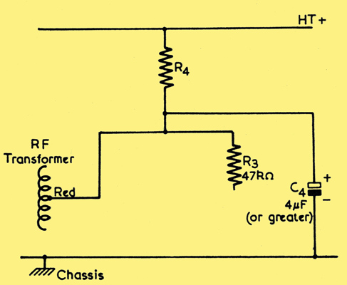
Fig 2.
In cases where the available HT voltage is too high, the simple dropping and decoupling circuit of Fig. 2 may be employed. When this arrangement is used it would be advisable to find the value of the dropping resistor, R4, experimentally whilst the secondary of the transformer is connected to the heater of the valve it is eventually intended to drive. The correct dropping resistor will be that which causes approximately 240 Volts to appear across the decoupling condenser, C4, under these conditions.
Tape Recorder Applications
The inductance of the transformer primary is set to a standard by the manufacturer before it leaves the factory. In consequence the frequency of operation can be selected within quite fine limits by varying the value of C2 in Fig. 1. The output of the transformer remains constant for changes in C2 between the limits 300 pF to 0.0025 μF. However, it is anticipated that the value of C2 will normally be made either 0.001 or 0.002 μF, or a value in between. At 0.001 μF the frequency of oscillation is 54 kHz, and at 0.002 μF 41 kHz.
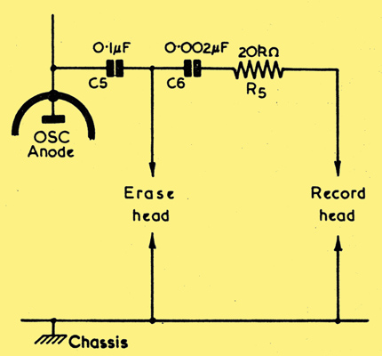
Fig 3.
It will be noted that these frequencies are those normally employed in tape recording for erase and bias voltages. In consequence, it is possible to employ the transformer not only to heat the first valve of the amplifier but also to provide erase and bias facilities. A suitable circuit for high impedance tape heads is illustrated in Fig. 3. The primary of the transformer in this circuit functions as a high-grade erase and bias oscillator coil and, as the writer has checked experimentally, functions equally well whether the secondary is loaded by a valve heater or not. Indeed, as it stands the transformer is attractive for the oscillator purpose alone; whilst yet another application could be the use of the secondary to light a pilot lamp or heat a Magic Eye recording level indicator. The illumination of either of these would then indicate that the erase and bias oscillator was functioning correctly when the amplifier was switched to the "Record" position.
|