|
In 2001 the author was invited to talk about the museum to some local Radio Societies and other groups. As valve audio had passed into history a demonstration was considered to be essential. This amplifier was the result.

The completed amplifier. The volume control, speaker connections and the screen grid connection to the AC/Pen.
The first successful mains powered audio output valve was the Mazda AC/Pen from 1930. Initially made with a B5 base cap and a side terminal for the screen grid connection. The driver valve was typically the AC/P, also from Mazda. It seemed appropriate to use these two valves in the amplifier.
A standard die-cast box was used as the chassis and as the amplifier was never intended for permanent use all power would be supplied from external sources through 4 mm sockets. The author did not have a 270 Ω resistor of adequate power rating for the output valve cathode resistor and so the valve was under-run with a low power 470 Ω resistor. The data for the AC/Pen indicates that cathode bias should be used. The other components were also selected from the 'Junk Box' with the exception of the output transformer. This was, and in 2020 still is, available from RS components.
The AC/Pen with 250 Volts HT needs an output transformer impedance of 7,500 Ω. The speaker impedance was set to 8 Ω. Looking at the transformer design chart a suitable set of connections would be: pin 1 to HT, pin 4 to anode. The speaker being across D to A. The tap at pin 3 was used to connect the screen grid - some shift to an ultra linear connection.

Details of the output transformer.
All ground connections for each stage are returned to a single point and the stage ground points later connected to the input socket.

The underside of the chassis.
The design is utterly basic as the requirement was to show early valves playing music from the 1930s in the demonstrations. Whilst not optimised to the standards of the 1930s, using modern components the sound is most acceptable - but not hi-fi.

Circuit diagram.
After may years as an ornament, it was decided to see exactly what the amplifier could do in terms of output power and frequency response. To start with the amplifier was silent. The AC/Pen has straight rod pins and the vintage valve-holder has no internal springs. A little corrosion and no contact. Cleaning up the pins was somewhat successful but only if the valve was pushed slightly to one side. A MKT4 was to hand and that had split pins with a little spring to them. The valve was an over tight fit into the holder but worked well. Finally, to use the 90 year old AC/Pen, the pins were bent a small amount so proper contact was made with the holder.
The test set-up uses a sine wave from a modern function generator and the output waveform was viewed on the Tektronix oscilloscope. The latter also has a spectrum analyser function as well as true RMS measurements. The input amplitude was adjusted to the point where the third harmonic (3 kHz) just started to rise.
After the first tests a 680 Ω resistor was added in parallel to the 470 Ω cathode resistor reducing the bias resistor to 270 Ω. The aim being to increase the current to 32 mA. The current increased but the output did not. The AC/Pen was replaced by the beam tetrode MKT4 without circuit changes. The current rose to 32 mA and the response plotted.

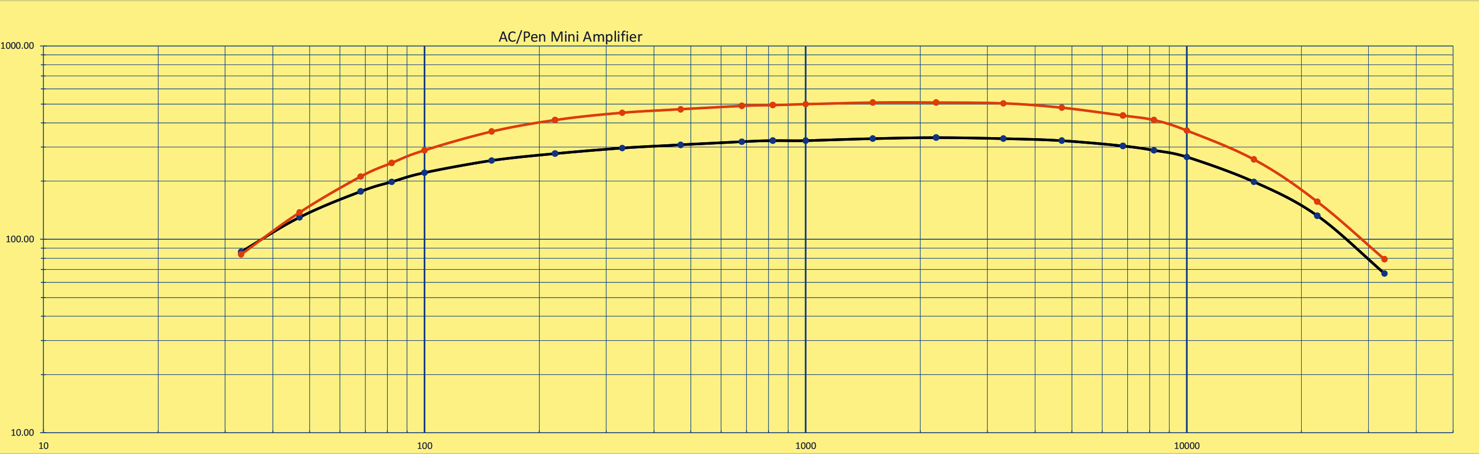
The measured performance mW : AC/Pen - HT of 230 Volts at 25 mA Black line.
The measured performance mW: MKT4 - HT of 250 Volts at 32 mA Orange line.

The rear of the chassis. HT and heater connectors.
Naturally the sound lacked bass but the volume through a modern Mission book-shelf speaker was more than adequate for the 7 x 4 metre garden office.
|