|
Origin of the circuit: some practical points.
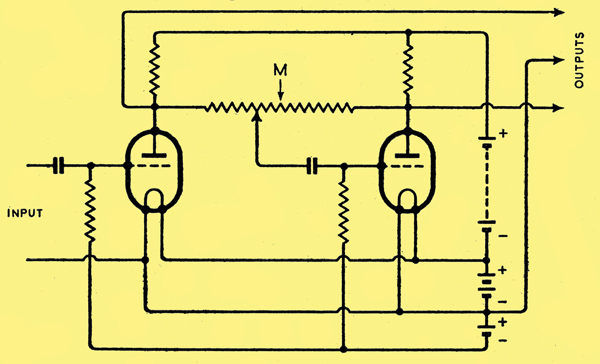
This circuit diagram is redrawn from Fig. 6 of the Patent specification mentioned in the text.
In the July issue of Wireless World Squadron Leader Scroggie describes a circuit which he aptly calls the See-Saw circuit, but which he distinguishes from the Paraphase circuit.
In British Patent No. 32 5833 I coined the word 'Paraphase' and if comparison be made between Fig. 6 of the patent and Fig. 4 of the article just mentioned, the two circuits will be found to be essentially identical: the only difference of any importance is that, in the patent drawing the tapping point on the resistance path connected between the two anodes from which the grid voltage of the second valve is derived is displaced, as it ought to be, a little towards the anode of the input valve. This was of course obviously essential in 1929 when high-gain valves were not in common use, but in my opinion it still is for reasons which will be given later. The self-balancing properties of this circuit were well known to me, and it was always used in commercial designs in preference to the more obvious connection given for example in Fig. 2 of the patent, but it is only fair to S /Ldr. Scroggie to mention that the self-balancing effect is not mentioned in the Patent, and I am indebted to him for drawing public attention to it. The circuit as such has, however, been described by various writers; see, for example, L W Hayes on page 950 of World Radio for 12th December, 1930, and Radio Designers'Handbook, p. I2. The circuit was used in the Science Museum receiver in 1930 and was chosen because of its self balancing properties to which I drew attention at the time.
Turning now to S /Ldr. Scroggiebs proposal to use a fixed centre-tapping from which to derive the grid voltage for the second valve, I fear that in practice this may give very bad results for the following reasons.
First, it is stated that so long as the resistors R5 and R6 are equal within commercial limits . . . the voltage balance adjusts itself. A pair of resistors marked 1 MΩ taken at random might easily differ by 40%, which is 10% more than the maximum difference contemplated in Fig. 5 of the article.
Secondly, the calculation of which the results are presented graphically in Fig. 5 take no account of the grid leak R7; clearly this is effectively in parallel with that part of the cross-connected anode-to-anode resistance lying between the tapping point and the electrical fulcrum - obviously this is only a small matter if valves of very high voltage gain be employed, but it operates to impede the balance.
Thirdly, the anode resistances may be unequal. It is therefore very much better to employ an adjustable tapping point, which is readily done by connecting a wire-wound potentiometer type resistor between R5 and R6 and taking the grid lead off from the movable connection: the correct balance point is then very easily found in one of two ways.
If the two anode resistances (50,000 Ω in S/Ldr Scroggiebs diagram) are known to be equal within, say, 5%, a pair of low resistance phones (or better, a step-down transformer with phones across its secondary) is connected in the common anode supply lead to the two valves and signals are applied to the grid of the first. On adjusting the tapping point a position will be found where the signals heard show a sharply defined minimum, which indicates of course that the phase-opposed alternating components of the anode currents are equal, and hence, that the alternating voltages at the points A, B, are equal to the same degree of accuracy as the values of two anode resistors.
Alternatively, if two precisely equal high-value resistors say of 1 MΩ each be connected in series between the two anodes and a capacitor in series with a pair of high resistance headphones be connected between the centre point and earth, the balance point can be determined as before. Whatever method is employed, it is important to do nothing which will affect materially the magnification given by the valves, or the balance will change on removal of the balancing components.
Once, the correct tapping-point has been set with a pair of reasonably similar valves, the self balancing effect is quite sufficient to compensate for subsequent changes in valve characteristic or for valve replacement; it is chiefly in this that the real value of the circuit lies.
When two valves of similar characteristics are not available or when the characteristics are not known, a good approximation to the optimum tapping point may be made by interchanging the two valves, and noting the change, if any, in the point of balance: the mean of the two settings may then be employed. If, however, a re-balance can be made whenever a valve is to be replaced it is obviously undesirable to adopt this practice.
Referring to Fig. 4, it is in many cases better to omit the capacitor shown in shunt with the common cathode resistor since this carries no alternating component when the valves are balanced and the omission of the capacitor helps the self balancing effect.
S/Ldr. Scroggie replies as follows:-
I am indebted to several corre-spondents for pointing out that my calculations of the See-Saw circuit did not take into account the loading effect of the grid leak (R7 in Fig. 1), and that they are correct only when its resistance is infinite. As one of them has pointed out, this condition can be achieved by a modification of the circuit, shown as Fig. A.
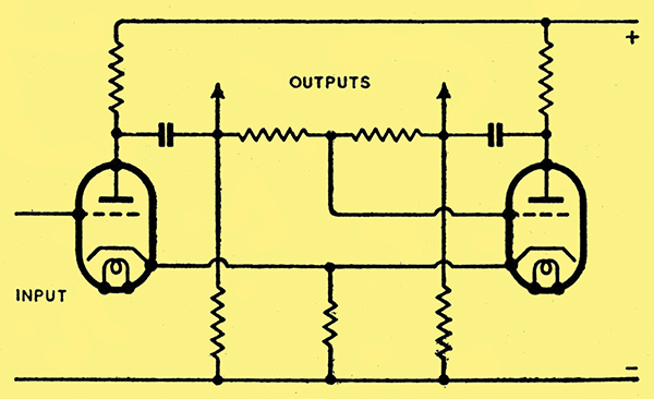
Fig. A. A modification of the original See-Saw circuit.
But I must admit that my original circuit (Fig. 4) showed R7 equal in value to R5 and R6 (1 MΩ). This is a reasonable practical assumption, and several readers have worked out the balance conditions for it.
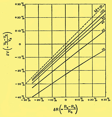
Fig. B. Percentage departure from voltage balance under conditions given in the text.
When plotted, they yield Fig. B, which should be compared with my original Fig. 5; It will be seen that the general character of the results is similar, but numerically the departure from balance when R5 and R6 are equal is somewhat increased. It is interesting to note that this increase is exactly neutralised if the valve gain, M, is increased by 50%.
As one reader has hinted, if the resistances of R5, R6 and R7 are very high, it may not be permissible to ignore the input capacitance of the valve. For example, it is unlikely to be less than 10 pF, which at a frequency of 10,000 Hz is 1.6 MΩ reactance, comparable with the resistances. If a high-amplification triode were used, the capacitance would be many times greater owing to Miller effect, which is an additional reason for using a tetrode or pentode. A correspondent has suggested the application of the see-saw system direct to the output stage. This would seem to be an economical and quite satisfactory arrangement provided that (a) the external grid drive can be provided at the required amplitude without distortion (this should not be a serious difficulty), and (b) the tapping from which the other grid drive is obtained is suitably adjusted, as it is unlikely that the voltage gain of an output stage would be sufficient to ensure a good enough balance otherwise.
Mr Carpenter has rightly pointed out that it is better to omit the cathode resistor by-pass capacitor when it is common to two similar push-pull valves. If it is not common, however, it is desirable to fit the capacitor in order to avoid loss of amplification.
In referring to resistors equal 'within commercial limits' I did not mean that resistors of unlimited tolerances should be used without any check, but that ordinary commercial types could be used after a rough test for equality within, say, 10%, and that it was unnecessary to use precision resistors, or a wire-wound potentiometer as advocated by Mr Carpenter. I assume, of course, that the amplifier is to be used for ordinary purposes, and not in some precision measurement system.
The name Paraphase has often been understood to apply to the particular phase-splitter circuit in which the grid drive for one valve is obtained from a tapping on the anode resistor of the other; and I confess that I have used it in this sense. I am glad to have it on the authority of the inventor himself that he gave it a much wider meaning, covering practically all RC push-pull amplifiers. This being so, the name 'see-saw' is useful for distinguishing one particular form of Paraphase circuit.
Some correspondents made the mistake of saying I assumed the characteristics of the two valves in this circuit to be identical. On the contrary, I said: there is obviously no necessity for this valve (i.e., the driver) to be of the same type as the phase-splitter valve, and to emphasise this point I started by showing the former as an arbitrary generator, which need not even be a valve at all! Except for an output stage, the question of equality of valve characteristics, on which Mr Carpenter lays stress, therefore does not arise. Nor does the necessity for equal anode resistances. There are, of course, some incidental advantages in symmetry.
Mr Carpenterbs tests for balance both necessitate close equality of two resistors. If facilities exist for obtaining such resistors (or better still, resistors differing by a specified percentage) it is simpler to use them as the anode-to-anode resistors in the see-saw circuit; and provided the stage gain is not less than about 40 (as it will be with tetrode or pentode) a satisfactory and permanent balance is automatically ensured, without the trouble of making periodical tests and adjustments. It was to draw attention to this great advantage of the see-saw circuit that my article was written.
|