|
Transitron type timebase.
One of the war-time radar developments [1] Radar Circuit Technique, Wireless World May 1946. Vol. LII. [2] IEE Radiolocation Convention Papers having immediate application to both television and cathode-ray oscilloscopes is a single-valve linear saw-tooth oscillator. It is of particular interest because its performance is outstandingly good and it is at the same time both simple and economical.
In essence it is a modification of the transitron time-base which has its origins in the Numans oscillator [3] The Numans Oscillator, K C Van Ryn, Experimental Wireless (now Wireless Engineer), December, 1924. Vol. II, p.134.. After lying dormant for over a decade the principle was revived under the new name of transitron [4] Negative Resistance and Devices for Obtaining it, E W Herold, Proc. Instn. Rad. Eng., October 1935. Vol. 23, p.1201 [5] The Transitron Oscillator, C Brunetti, Proc. Instn. Rad. Eng., February, 1939. Vol. 27, p.88, but its applications were envisaged chiefly as a sinewave oscillator using a tuned LC circuit. Its use as a sawtooth generator [6] Trigger Circuits, H J Reich, Electronics, August, 1939. was less widely realized, and it was not until 1940 that its capabilities appear to have been fully examined [7] Single-valve Time-base Circuit, B C Fleming-Williams, Wireless Engineer, April 1940. Vol. XVII, p. 161 [8] Versatile Oscillator,W T Cocking, Wireless World, September, 1940. Vol. XLVI, p. 390.
The war-time adaptation of it has resulted in an enormous improvement. In its present form it is really a combination of two things - the union of the pre-war transitron with the war-time Miller integrator - and although it still functions on transitron principles the details of its operation are very different.
Since it is a combination of two circuits it is convenient to consider them separately as far as possible. The Miller integrator will be dealt with first, for this is the heart of the new circuit in as much as it is responsible for the linearity of, the saw-tooth waveform. It is called the Miller integrator because it depends for its action upon the well-known Miller effect. That is, the effect which makes the input capacitance of a valve (1 + A) times its grid-anode capacitance, where A is the voltage amplification between the grid and anode circuits.
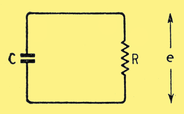
Fig. 1. The basis of a time-base. A charged capacitor is allowed to discharge slowly through a resistor.
In the normal time-base a capacitance is charged slowly through a resistance from the HT supply, and then discharged rapidly through a valve. Alternatively, a capacitance is charged rapidly through a valve and then discharged slowly through a resistance. Considering this latter form, if C in Fig. 1 is charged to an initial voltage E and is allowed to discharge through R, the voltage e at any time t after the start of discharge is e = Eℇ-tT, where T = CR.
The voltage falls exponentially. The slope de/dt = (E/T)ℇ-tT.
In practice e is permitted to change only a small amount and for this small change the discharge is considered to be linear. Thus, if a change of slope during the discharge of 2% is permissible ℇ-tT = 0.98 as a minimum and t/T = 0.02 as a maximum. Therefore; the change of voltage across C is restricted to 2% of the initial voltage on C.
For time-base purposes, a change of 40 Volts across C is usually desirable, and this demands an initial voltage, and therefore an HT supply, of 2,000 Volts. It is usually uneconomical to provide this.
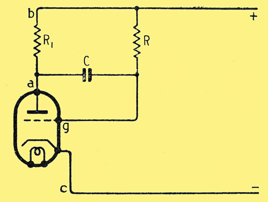
Fig. 2. The Miller integrator adapted for a time-base.
The Miller integrator in the form adapted for a time-base is shown in Fig. 2. R1 is usually very small compared with R, so that to a close approximation the valve and R1 can be considered as a generator in series with R and C.
The action is most easily understood by starting with C charged to the full HT voltage and with the valve drawing some anode current, without bothering for the moment about how the capacitance is charged. The valve current produces a voltage drop across R1 so that the anode a is negative with respect to + HT, - the point b. Therefore, the grid g is negative with respect to b by the sum of the drop across R1 and the HT voltage. But the cathode c is negative with respect to b by the HT voltage. Consequently, g is negative with respect to c by the voltage drop along R1. Grid current, therefore, does not flow.
As C discharges the voltage across ag falls and so g becomes less negative with respect to c. This increases the anode current and so makes a more negative with respect to b. As Vag falls Vba increases (Vag is the voltage by which a is more positive than g). If the two were equal the voltage Vbg would be constant and the current through R would be constant. This current, however, is the capacitance discharge current and a constant current flowing out of a capacitance means a linear fall of voltage across it.
This cannot be achieved for, if Vbg were constant, Vgc would also be constant and there would be no change of grid voltage to produce Vba. However, by making the amplification large Vba can be much larger than Vgc and the linearity can approach perfection.
It is not difficult to show that if A is the voltage amplification (≈gmR1) the discharge current i = (E/R)ℇ-tT where T = CR(1+A). As far as current is concerned the circuit behaves as if the capacitance were (1 + A) times its actual value.
The anode voltage of the valve varies in the form
Vab = E(1 - A (1 - ℇ-tT )).
It varies as if C were (1 + A) times its actual value and E were A times the true voltage. With a screened pentode gm may be 6 mA/V and R1 may be 10 kΩ, making A = 60. Now A can easily be 250 Volts, so that the effective voltage is, 15,000 Volts. For 2% linearity, 0.02 of this or 300 Volts, would be available as output but for one limitation. The maximum output must be less than the real HT voltage. A linear output is obtained only if the valve is acting as a linear amplifier. The maximum possible output is about 80% of the real voltage, and to give a factor of safety it should be rather less than this figure.
When acting as a self-oscillator, the output obtainable is further restricted by the transitron action and is about 20% of the HT voltage. For a 250 Volt supply the output is about 50 Volts, but for this 50 Volts the linearity is as if 15,000 Volts were acting in the circuit.
The distortion is therefore only (50 × 100)/15,000 = 0.3%
Using a pentode, only the control grid, cathode and anode are needed for this linearizing action and the screen and suppressor grids are available for other use. If they are resistance-capacitance coupled a transitron-type circuit is formed and a self-oscillating linear time-base is obtained. The circuit is shown in Fig. 3.
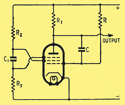
Fig. 3. The combination of the Miller integrator with a transitron gives a linear saw-tooth oscillator.
The action depends upon the ability of the suppressor G3 to control the ratio of the anode and screen currents. If the potential of G3 is changed negatively from zero it reduces anode and increases screen current, slowly at first and then quite rapidly. At zero Volts the anode current might be 10 mA and the screen current 2.5 mA. When G3 is very negative, however, the anode current may be zero and the screen current 10-12 mA.
To a first approximation the cathode current is independent of the potential of G3 and this electrode acts to control the division of the current between G2 and anode.
Now consider Fig. 3 at an instant when C is fully charged and the valve is conducting. At this time G3 is at or near cathode potential and the screen current is at its minimum. The voltage on G2 is thus a maximum. The valve then functions more or less normally as an amplifier linearizing, the discharge of C in the manner already described.
If the potentials of G2 and G3 were constant the action would be identical, but because the G1 potential is changing positively, the G2 current is increasing. This means the potential of G2 is falling. The potential of G3 does not follow this change of voltage of G2 at all well, however, for the time-constant C1 R3 is much less than CR (1 + A).
The main effect, therefore, is rather like that of a pentode amplifier without a screen-grid by-pass capacitor, and a form of negative feedback occurs reducing the amplification somewhat.
As this process goes on the total cathode current is increasing as well as the individual anode and G2 currents, but the ratio of anode to screen currents is substantially constant. Now R1 and R2 are of the same order of magnitude, therefore, the voltage change at the anode is greater than that at the screen and at length the anode potential drops to such a degree that its field acting through G3 is no longer sufficient to collect the normal proportion of electrons passing G2. These consequently fall back to G2 and increase its current, thus dropping the G2 voltage.
This change of voltage is passed to G3 through C1 and makes it negative. This further reduces anode and increases G2 current, and so makes G3 still more negative. The action is cumulative and there is a very rapid transition to the flyback state with anode current cut-off, the G2 current a maximum and its voltage a minimum and G3 highly negative.
As anode current is cut-off, there is no voltagedrop across R1. The voltage across. C is less than that of the HT supply, consequently G1 is positive with respect to cathode and C now charges rapidly from the HT supply through R1 and the G1 - cathode path of the valve. This positive G1 potential tends to increase the G2 current and so reduce the G2 potential further and make G3 still more negative.
The time constant C1 R3 is finite and G3 cannot remain negative indefinitely. It is, however, larger than the discharge time constant, comprising only C, R1 and the grid-cathode resistance of the valve. When C is nearly fully charged the G1 grid potential becomes nearly zero and reduces the G2 current. There is a rise of G2 potential and also of G3. The anode potential is also substantially at the full HT voltage. The rising G3 potential thus permits the anode to draw current again and so reduces the G2 current. This makes the G2 potential rise further and so G3 goes still further in the positive direction. Again there is a cumulative action and a very rapid change-over to the initial condition of G3 at about zero volts and G2 at its maximum.
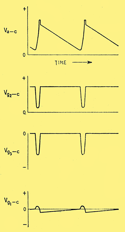
Fig 4. Voltage waveforms on the various electrodes of the valve in the circuit of Fig. 3.
The various voltage waveforms are sketched in Fig. 4, and well illustrate the action. Synchronization can obviously be effected by applying a negative-going pulse to G2 or G3 at a time prior to that at which the discharge would naturally occur.
The writer has used the circuit of Fig. 3 at 50 Hz with a TSP4 valve. With a 220 Volt HT supply an output at the anode of about 40 Volts is obtainable with C = 0.02μF; C1 = 0.01 μF, R = 4MΩ, R1 = R2 = 10 kΩ, and R3 = 0.5 MΩ R should be variable as a frequency control. A variable output can be secured at low-frequencies by making R1 a potentiometer, and taking the output from the slider.
The fly-back time is governed mainly by the value of C and can be increased by reducing this capacitance while increasing R to keep the product constant. The above values give a scan-to-flyback ratio of the order of 10:1. The TSP4 is not essential and the EF50 should be equally suitable.
In many cases the fact that the output is a negative-going saw-tooth is a disadvantage of the circuit. A positive-going output can be obtained from the cathode, but only about one-half the output can be secured. In addition, the G2 circuit must be decoupled to cathode.
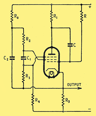
Fig. 5. Circuit giving a positive-going saw-tooth output at the cathode.
The arrangement of Fig. 5 is satisfactory at 10 kHz with C = C1 = 100 pF; C = 0.1 μF; R = 4 MΩ, R1 = R2 = R3 = 10 kΩ; R3 = 0.5 MΩ; R4 = 1 MΩ; R6 = 20 kΩ. A TSP4 was again used and an output of about 20 Volts amplitude secured at the cathode.
The cathode output is limited by two factors. The first is that R6 is virtually in parallel with R5 as far as voltage changes are concerned, but they are in series for direct current. If the voltage on G3 is to be high enough for satisfactory transitron action, therefore, the values of both R5 and R6 are limited. The second factor is R1; at least one-half of the total output of the valve is developed across this resistance and must be if good linearity and transitron action are to be secured.
References
- Radar Circuit Technique, Wireless World May 1946. Vol. LII.
- IEE Radiolocation Convention Papers
- The Numans Oscillator, K C Van Ryn, Experimental Wireless (now Wireless Engineer), December, 1924. Vol. II, p.134.
- Negative Resistance and Devices for Obtaining it, E W Herold, Proc. Instn. Rad. Eng., October 1935. Vol. 23, p.1201
- The Transitron Oscillator, C Brunetti, Proc. Instn. Rad. Eng., February, 1939. Vol. 27, p.88
- Trigger Circuits, H J Reich, Electronics, August, 1939.
- Single-valve Time-base Circuit, B C Fleming-Williams, Wireless Engineer, April 1940. Vol. XVII, p. 161
- Versatile Oscillator,W T Cocking, Wireless World, September, 1940. Vol. XLVI, p. 390
|