|
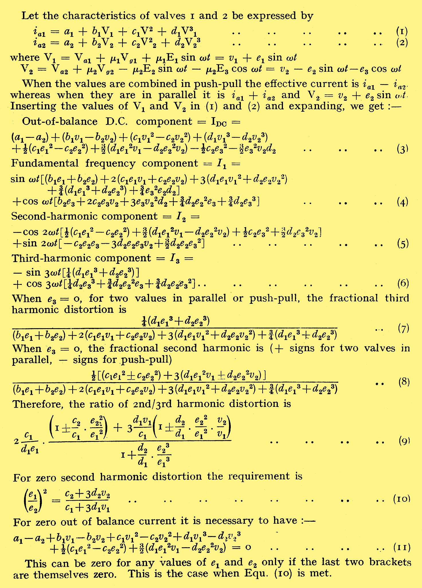
Effect of Minor Imperfections.
One of the more important reasons for adopting push-pull amplification, especially in an output stage, lies in the fact that under ideal conditions all even-order harmonics, introduced by curvature of the valve characteristics, are balanced out and do not appear in the output. In addition to this, the mean anode currents of the valves act in opposition in the output transformer and the core consequently works under better conditions. Because of this transformer distortion is also reduced.
It is important to notice that the push-pull connection only reduces even-order harmonics. Consequently, its use is of value only if the distortion introduced by the valves is predominantly of this kind. This is so with triodes and for long no other valves were used in push-pull.
When operated under optimum conditions for a single output valve, a pentode or tetrode usually introduces more third than second harmonic. The use of a pair of such valves in push-pull then gives relatively little advantage over a pair in parallel, but there is still some advantage, largely because of the improved conditions in the output transformer brought about by the removal of the direct polarizing current.
The distortion introduced by a tetrode or pentode depends very much upon the magnitude of its load resistance, however. With a low value of load the distortion is predominantly second harmonic, just as with a triode, and this distortion tends to decrease as the load is increased, again just as with a triode. Unlike the triode, however, third harmonic distortion grows rapidly as the load resistance is increased. Although small when this resistance is small it greatly exceeds the second harmonic when it becomes high.
When pentodes are used in push-pull, therefore, it usually pays to work with an effective load on each which is much less than the optimum for the non push-pull case. The third-harmonic distortion is reduced and the second-harmonic distortion is balanced out by the push-pull connection. While there is no doubt at all about the value of push-pull in both theory and practice, many people realize that the ideal conditions which are usually assumed in theoretical discussions do not exist in practice. They realize, for instance, that the two valves of a push-pull stage are never exactly alike, and they wonder how much the performance is affected by this. Then, again, they know that various balancing schemes are sometimes recommended and they wonder if they are necessary when other amplifiers perform satisfactorily without them.
It is not easy to find answers to questions such as these and very little definite information on the subject has been published. The simplest method of attacking the problem is to express the characteristics of the valves by power series, but even if only a few terms are taken the expressions become very cumbersome, and it is not easy to take the load impedance into account.
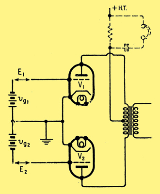
The basic push-pull circuit. The dotted components in the HT lead are often inserted when balancing a stage.
The equations in the Appendix show the second and third-harmonic distortion produced by valves having characteristics which can be represented by cubic equations, ignoring the effect of the load. The distortion for a pair of valves in either parallel or push-pull is given. The signal voltages are represented by e1 for one valve and e2 + e3, for the other; e1 and e2 are in opposite phase for push-pull and e3 is in phase quadrature. This last term is included so that the case when the input voltages to the two valves are not exactly in opposite phase can be considered; e1 on the one hand and e2 and e3, on the other are respectively μ1 and μ2 times the actual input voltages E1, E2 and E3.
First of all, e3 will be taken as zero. It can be seen from the equations in the Appendix that both the fundamental and third- harmonic components are the same whether the valves are in parallel or in push-pull. With the latter circuit both the out-of-balance direct current in the out-put transformer and the second-harmonic distortion can be reduced to zero by the adjustment of the relative values of v1, v2, e1 and e2.
If the two valves are exactly alike the requirement for perfect balance is v1 = v2 and e1 = e2 that is, the two valves must have the same grid bias and their inputs must have the same amplitude, and be in opposite phase.
In this case the fundamental frequency current in the HT lead is also zero. It is given by Equation (4) by writing minus signs instead of + between the pairs of terms in brackets. Because of this a favourite way of balancing a push-pull amplifier is to insert a resistance shunted by a pair of phones in the HT lead, as shown dotted in Fig. 1, and to adjust the relative values of the input voltages E1 and E2 for zero fundamental tone in the phones.
Of course, in this particular case, since the output stage is assumed itself to be perfectly balanced, all that is done is to equalize E1 and E2 and so to correct for imperfections in the preceding stage.
Balancing Adjustments
When the valves are not identical, second-harmonic distortion in the output and the out-of-balance mean current can both be brought to zero by adjusting the values of e1/e2 and v1/v2. With no signal the out-of-balance current depends only on v1/v2, but the condition for zero second- harmonic distortion depends on both e1/e2 and v1/v2. . The out-of-balance current with a signal depends also on both e1/e2 and v1/v2, so that the zero signal balance is not necessarily maintained when a signal is applied.
When e3 = 0, Equation (3) shows that the out-of-balance current can be brought to zero even when the valves are not alike by adjusting v1/v2 with no applied signal. Equation (5) shows that the second harmonic in the output can also be brought to zero even although the valves are not alike by adjusting e1/e2. When this is done the signal-dependent terms in Equation (3) are also zero, so that just as in the case of identical valves the second-harmonic and out-of-balance currents can be made zero for all amplitudes of input.
However, the fundamental frequency component in the HT lead (Equation (4) with - signs before each group of terms with subscripts 2) is no longer necessarily zero. This is also obvious on physical grounds, for if the valves are unlike they introduce different percentages of second harmonic. When adjusted for zero total second harmonic in the output each valve must be giving the same amplitude of second-harmonic output. But if the percentages are different the fundamental outputs must also be different, and so they cannot balance in the HT lead.
It is thus clear that in the general case the popular method of balancing an amplifier for zero fundamental component in the HT lead will not necessarily give zero second harmonic in the output. It will only do so, in fact, if the output valves are identical.
Strictly speaking, therefore, the right way of adjusting e2/e1 is directly for minimum second-harmonic distortion in the output. This is very inconvenient, however, for it demands the connection of a filter in the output to suppress the strong fundamental component.
It has been assumed so far that the input voltages to the two values are precisely in opposite phase; i.e., e3 = 0. In practice, phase errors occur towards the two ends of the frequency range. They occur chiefly in the phase-splitting circuits. They can be represented by a voltage E3 which is 90 ° out of phase with the input E2 to one of the valves, E2 itself being exactly in opposite phase to E1.
Phase Unbalance
The effect of E3 is to produce output currents in quadrature to those caused by E1 and E2, but through interaction between them it does also produce currents additive to the main ones. Because of the quadrature currents it becomes impossible to balance second-harmonic distortion to zero and equality of mean anode currents cannot be maintained at all signal levels.
However, these effects are very small in practice because it is not difficult to keep the phase errors small. It is by no means easy to make them zero but in a common type of phase-splitter they can be such that E3 does not exceed about 3% of E2.
There are so many possible causes of unbalance in a push-pull stage that it might be thought that a balancing adjustment would be essential. This is not so, however, for a surprisingly large amount of unbalance can often be tolerated.
In general, balancing adjustments are undesirable if their use can be avoided, for their correct use demands some degree of skill. It is, therefore, the usual commercial practice to dispense with them. This is done by determining a permissible degree of unbalance which affects the performance negligibly, and then designing the equipment so that this degree of unbalance is not exceeded with any normal variations of components and valves.
Under such conditions neither the out-of-balance current nor the second-harmonic distortion will usually be zero, but this does not matter provided that the resulting distortion is small enough. An output stage might, for instance, be designed for 2% third-harmonic distortion at full output. The second-harmonic distortion might vary from the ideal zero to, perhaps, 1% according to the degree of balance achieved. The addition of 1% second harmonic to a stage already giving 2% third-harmonic distortion is not likely to be noticeable to the ear. The total distortion is increased to 100√(0.022 + 0.012) = 2.5%, little over 1 db. Moreover, the ear is more tolerant of second- than of third-harmonic distortion. It is, therefore, almost certain that the extra distortion would not be aurally detectable.
However, this may be, it is certain that there is some degree of second-harmonic distortion relative to the third harmonic which cannot be detected in any listening test. Provided that the second harmonic can be kept below this figure, therefore, its presence is immaterial, and if an amplifier can be designed which is inherently well enough balanced to keep the distortion below this figure its performance is as good as one more perfectly balanced. It is also much more satisfactory in practice.
In order to determine how much unbalance is permissible in an amplifier it is necessary to know how much second-harmonic distortion can be allowed. This can only be settled by elaborate listening tests with large numbers of observers. For present purposes it will be assumed that an amount of second harmonic equal to the third harmonic is unimportant. This is a 3 db increase in distortion from an 'ideal' level of -34 db, assuming that 2% third harmonic is the target. The distortion level thus rises from the 'ideal' -34 db to -31 db and this in itself would not be readily detected by ear. When the greater tolerance of the ear to second-harmonic distortion is taken into account; it seems certain that its presence in this degree is unimportant.
At present this must be largely a matter of opinion, and it is possible to work out the permissible unbalances for any desired ratio of 2nd/3rd harmonic distortion. In the following examples, however, a figure of unity for this ratio is taken as the maximum permissible.
For the present assume that there is no phase unbalance (e3 = 0). Then Equation (9) in the Appendix gives the ratio of 2nd/ 3rd harmonic distortion. The ratio does not depend only on the ratios e2/e1, v2/v1, c2/c1, d2/d1, but also on c1/d1, e1 and v1. It is not, therefore, possible to derive a general solution applicable to all valves, but it is necessary to work out the permissible unbalances far each case.
The best that can be done, therefore, is to pick a typical case and the following values will be assumed: b1 = 2 × 10⁻⁴, c1 = -3 × 10⁻⁷, d1 = 1.25 × 10⁻⁹, e1 = 120 V, v1 = 180 V. These values correspond to a fictitious valve having 300 V HT, -40 V grid bias, μ = 3 and a signal input of 40 V peak. A single valve, or a pair in parallel, produce 2% third-harmonic distortion and 10% second harmonic. It is required to determine how the second-harmonic distortion of a pair in push-pull varies with the various out-of-balance elements.
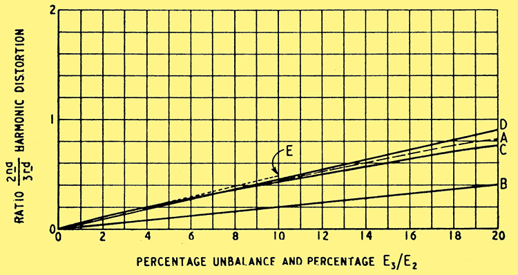
Fig. 2. The effect on the ratio of 2nd/3rd harmonic distortion of various kinds of balance is shown here.
Curve A c2/c1 = d2/d1 = v2/v1 = 1, e1 = 0, e2/e1 varying.
Curve B e2/e1 = d2/d1 = v2/v1 = 1, e3 = 0, c2/c1 varying.
Curve C e2/e1 = c2/c1 = v2/v1 = 1, e3 = 0, d2/d1 varying.
Curve D e2/e1 = c2/c1 = d2/d1 = 1, e3 = 0, v2/v1 varying.
Curve E e2/e1 = c2/c1 = d2/d1 = v2/v1 = 1, e3/e2 varying.
This is done by taking the above values for the valves and calculating the 2nd/ 3rd harmonic ratios with the aid of Equation (9). The results are shown in Fig. 2; curve A shows how the harmonic ratio varies as e2/e1 varies for the case when the valves are identical and v1/v2. For unity distortion ratio over 20% unbalance of the input voltages is permissible. Curve B shows the effect, with e2 = e1, d2 = d1 of varying c2/c1 and curve C illustrates the effect of varying d2/d1 with c2 = c1 . Even with 20% difference between either of these valve constants the second harmonic does not exceed 0.4 of the third.
The effect of varying v2/v1 is shown in curve D. This, however, is not a grid-bias variation but one of total voltage. It can be converted to one of grid-bias variation in this instance by multiplying the 'Percentage Unbalance' scale in Fig. 1 by 1.5. By using equation (13) the effect of varying e3/e2 can be computed and is shown in curve E.
In a practical case these variations may all occur together but it is clear from Fig. 2 that in order of importance the various causes of unbalance are e3/e2, v2/v1, e2/e1, c2/c1, d2/d1 . This is rather a fortunate order, for the valve variations are of least importance and it is these which are least under the control of the amplifier designer. It is well to allow a maximum variation here and it is not unreasonable to take c2/c1 = d2/d1 = 1.2; that is, 20% unbalance between valves.
If the valves are operated in the usual way with a common bias resistor v2/v1 = 1. The out-of-balance current in the output transformer rarely exceeds 10 mA, in practice, and this causes negligible distortion when a well designed transformer having a silicon-steel core is used.
The phase unbalance between the inputs is usually negligible over the major part of the audio-frequency spectrum. At very low and very high frequencies it becomes of appreciable magnitude but with good design it is not large. It occurs chiefly in the phase-splitter and may amount to about 3%. The value of e3/e2 will, therefore, be taken as 0.03.
With these values as reasonable tolerances to allow for variations in values and for some phase unbalance the ratio of 2nd to 3rd harmonic distortion for various values of e2/e1 can now be calculated and the permissible input unbalance so determined.
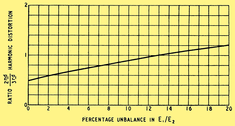
Fig. 3. The effect of varying e2/e1 is shown here for the case when v2/v1 = 1, c2/c1 = d2/d1 = 1.2, and e3/e2 = 0.03.
The result is shown by the curve of Fig. 3 and it will be seen that for unity distortion ratio an input unbalance of as much as 13% can be allowed. This is for the worst case when the input unbalance is in the same sense as the others; when it is opposing, a much bigger tolerance is permissible.
Grid Current Effects
It will be clear from all this that a push-pull stage is very far from being critical and what at first appear to be quite large amounts of unbalance have quite a small effect on the performance. This is in accord with practical experience.
In the foregoing it has been assumed that there is no limit to the permissible value of E1/E2 (e1/e2) other than that set by the appearance of excessive second-harmonic distortion. This is not the case, in practice, however, for if the two input voltages are dissimilar then one valve will run into grid current earlier than the other unless the valve with the larger input has a proportionately higher grid bias. Very serious distortion usually occurs when grid current starts, and if one valve draws grid current before the other the amplifier is overloading before the other valve is giving its full output.
Conditions in this respect are likely to be at their worst when an amplifier carefully balanced for zero second-harmonic and out-of-balance currents! The poorer valve of the two may need the greater input and the smaller grid bias for balance.
The tolerance permissible on E1/E2 is thus likely to be tighter for the avoidance of marked disparities in the grid-current overload points of the two valves than for avoidance of second-harmonic distortion. If the bias is 40 V and the maximum input is 40 V peak, then with the 13% tolerance found earlier, the input to the other valve will be only 35.4 V. As the power output is proportional to the square of the input voltages it will be about (75.4/80)2 = 0.89 of that which would be obtained with equal input voltages and identical valves.
The loss is not large, but a somewhat tighter input tolerance would seem desirable. It is suggested that an input tolerance of ± 5 per cent should be aimed at in designing the preceding stages and that there should be not more than 3% phase unbalance at high and low frequencies, This permits rather greater tolerances on valves than have been considered in the foregoing.
No attempt at balancing second-harmonic distortion to zero should normally be made and it is only necessary to balance the mean anode currents in exceptional cases or when high-permeability core material is used in the output transformer.
Appendix
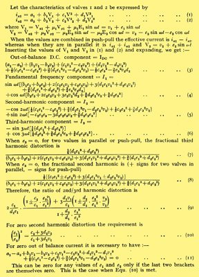
|