|
Principles of operation.
The multivibrator has latterly attained great importance, and much discussion has taken place as to how its principle of action should be presented to students and even as to how it operates, especially as the oscillograms given in several of the most reputable textbooks are misleading and some are incorrect.
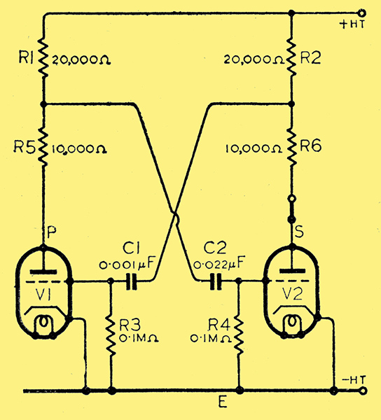
Fig. 1. Circuit of a multivibrator, with additional resistances R5 and R6 inserted.
It is suggested that the principle of action of the multivibrator should be dealt with after the students have seen the cathode-ray oscillograms referred to below and that the explanation and the derivation of the waveforms should be based upon the waveforms of anode currents in the asymmetrical multivibrator. These waveforms are easily obtained by inserting additional resistances R5 and R6, as shown in Fig. 1. That these resistances have little effect upon the waveforms can be checked by making R5 and R6 small and using an amplifier stage on the oscillograph. In practice, it is simpler to use values such as those suggested in Fig. 1, thereby avoiding having to switch over from amplifier to 'direct' or vice versa when shifting the oscillograph tappings to the circuit.
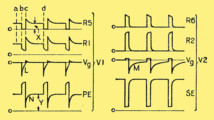
Fig. 2. Typical waveforms as developed by the circuit of Fig. 1.
The oscillograms in Fig. 2 are typical waveforms of the PDbs across R5, etc. It is extremely important that the zero axis should be inserted for each oscillogram. This axis can be obtained by merely disconnecting the HT supply.
Let us first assume that the switch S in the anode circuit of V2 is open. Anode current flows through V1; C2 is charged to the PD existing across R5 and V1, and the PD across C1 becomes equal to the voltage of the HT supply. The various PDbs are as represented at instant a in Fig. 2.
Suppose the switch to be closed at instant b. The PD across R2 due to the anode current of V2 reduces the PD across R6 and V2 so that C1 discharges through V2 and R3, making the grid end of R3 negative relatively to the cathode end. Consequently, the anode current of V1 and the PD across R1 are reduced. The increased PD across R5 and V1 sends a charging current to C2, making the grid of V2 positive relatively to its cathode, thereby accentuating the growth of anode current in V2 responsible for starting the cycle of reactions. The latter, though taking long to describe, occur at such a rate that the anode current of V2 increases to its maximum and that of V1 falls to zero simultaneously and practically instantaneously.
The anode current of V1 remains zero as long as the grid of V1 remains sufficiently negative. Owing, however, to C1 being small, it discharges quickly, as indicated by curve L. Also, the PD across PE increases instantly at b, and would be equal to the HT voltage had it not been for the voltage drop in R1 due to the charging current of C2.
At instant c, the combination of anode and grid voltages on V1 is such as to allow anode current to flow, and the reactions, described earlier, follow one another but in the reverse direction. Hence, the anode current of V1 rises instantly to its maximum while that of V2 falls to zero equally suddenly. Capacitor C2 now discharges through V1 and R4; but owing to the time constant of circuit C2 - R4 being far greater than that of C1 - R3, C2 discharges comparatively slowly. Consequently, the grid of V2 is maintained negative for a correspondingly long time, as shown by curve M in Fig. 2. The shape of M is not quite exponential owing to the variation of the PD across R5 and V1.
At instant c, the PD across SE increases almost instantly to that of the HT supply, any delay being due to the charging current of C1 flowing through R2. But since C1 is relatively small, this delay is also small. That the PD across SE during interval cd is equal to the HT voltage can easily be demonstrated by opening switch S.
Let us next consider what is happening at V1 during the interval cd. From the oscillogram for the PD across R5, we find that at c, the anode current suddenly grows to its maximum, as explained above, and then falls to a steady value corresponding to X. This transient effect is due to the corresponding positive potential on the grid of V1 caused by the charging current of C1. As the anode current of V1 falls to a steady value, the PD across PE increases, as shown by curve N, to a steady value Y. That X and Y represent the corresponding values under static conditions can be checked by opening switch S and noting the deflections when the oscillograph is connected across R5 and PE respectively.
At c, the positive potential on the grid of V1 is accompanied by grid current of such a value that most of the charging current of C1 flows via the grid. Consequently, the corresponding PD across R3 is very small; and owing to the smallness of C1 the latter is quickly charged and the grid-cathode voltage falls to zero accordingly.
At instant d, the negative grid voltage on V2 has decreased to such an extent that anode current begins to flow in V2, thereby producing reactions similar to those which occurred when switch S was closed.
During interval bc, most of the charging current of C2 flows as grid current in V2, so that the grid potential of the latter becomes only slightly positive. Also, during this interval, the PD across SE is comparatively small owing to the large voltage drop in R2 and R6.
It will now be evident that the duration of intervals bc and cd depends upon the rate of discharge of C1 and C2 respectively. Hence, the frequency of the oscillations is determined mainly by the time constants of circuits C1 - R3 and C2 - R4; While the asymmetry of the oscillations depends upon the relative values of these time constants. Also, it is seen from Fig. 2 that during the latter part of interval cd, valve V1 is operating under static conditions and is just waiting for C2 to discharge until the grid potential of V2 has fallen sufficiently for anode current to commence.
We may summarise the above treatment thus:
- The anode currents of an asymmetric multivibrator can be drawn roughly as complementary rectangles of unequal widths.
- When the anode current is zero, the grid potential is negative but decreasing at a rate depending upon the time constant of the grid capacitor and leak, and the anode-cathode voltage tends to rise to the HT value.
- When anode current is flowing, the grid voltage may be slightly positive and decreasing, and the anode-cathode voltage tends to rise to its static value.
|