|
Explaining their operation.
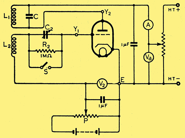
.Fig. 1. Circuit of a squegging oscillator: The provision of meters and of means for fine adjustment of operating voltages is of course incidental to the investigation of the behaviour of the oscillator, and not essential to its operation.
It is well known that in a valve oscillator of the type shown in Fig. 1 the oscillations may, under certain conditions, be continually starting and stopping, a phenomenon known as 'squegging'. Although this effect is sometimes turned to practical account - for example, in crude modulated oscillators - it does not seem to be satisfactorily explained in text-books. It is not sufficient to say that the time constant, C2R2, of the grid capacitor and leak must be large, since it is found that, with a given time constant, a triode may generate oscillations of constant amplitude when the coupling between L1 and L2 is loose, but may squeg when the coupling is tightened.
The double-beam cathode-ray oscillograph is particularly convenient for investigating the action of a squegging oscillator, as it enables the grid-cathode and the anode-cathode voltages to be observed simultaneously. In the actual oscillator investigated, C2 was a 3-dial decade capacitor having a total capacitance of about 1 μF; and points E, Y1 and Y2 were connected to the corresponding plates of the CRO, so that the oscillograms represented the DC as well as the AC components of the voltages.
With switch S open, zero grid bias from P, and C2 adjusted to, say, 0.05 μF, suppose the coupling between L1 and L2 to be tightened. The first effect is to generate continuous oscillations; but when the coupling exceeds a certain value, the amplitude of the oscillations is modulated, and further increase in the coupling produces pulses of oscillations spaced relatively far apart.
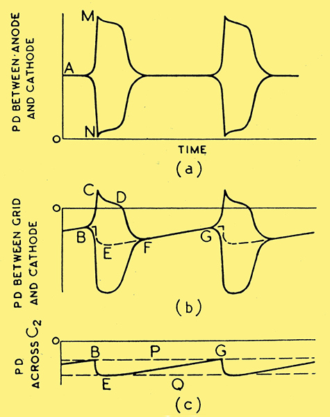
Fig. 2. Typical 'envelopes' of the RF oscillations.
With the time base of the CRO set to a low speed, it is possible to trace the envelopes of the RF voltages. Typical envelopes derived from such oscillograms are shown in Fig. 2. For this particular series the coupling was made as tight as possible. With slightly less coupling the initial tips M and N in the anode-cathode PD disappear. Curve (c) in Fig. 2 was obtained by connecting the oscillograph across grid capacitor C2; and the dotted line in Fig. 2 (b) indicates the phase relationship between this curve and that of the grid-anode voltage.
At instant B the negative potential of the grid relative to the cathode has decreased to a value that is found to be the cut-off bias of the valve under static conditions with anode voltage oA. Anode current begins to flow, and the oscillations increase quickly in amplitude. The amplitude of the EMF induced in L2 increases sufficiently to send the grid considerably positive during each positive half-cycle. The corresponding grid currents charge C2 so that the PD across the latter follows curve BE, and the positive peaks of the grid-cathode voltage follow curve CD. The pulses of grid current decrease in amplitude so quickly that they are soon only just sufficient to compensate for the leakage through R2. These positive peaks of grid voltage produce pulses of anode current and thereby help in maintaining the oscillations in circuit L1C.
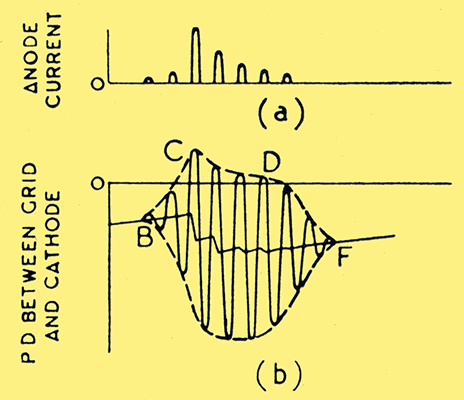
Fig. 3. Analysing an oscillation pulse.
Fig. 3 (b) has been drawn (but not to scale) to indicate what is going on inside the envelope of Fig. 2 (b); and the zig-zag line between B and F represents the PD across C2 during the squeg. The fact that the PD across C2 does tend to be a saw-tooth wave can be demonstrated by using relatively low values of R2 and C2 with the oscillator generating continuous waves. It is seen that during CD there are pulses of anode current of decreasing amplitude as in Fig. 3 (a), and the corresponding energy supplied from the HT source tends to maintain oscillations in LC. After instant D, however, the pulses of anode current decrease rapidly and the oscillations are quickly damped out, the rate of damping being dependent upon the decay factor, R/2L, of coil L1.
During interval FG, capacitor C2 is discharging through R2, and the grid bias decreases until, at G, anode current commences once more.
The influence of the mean grid-cathode PD upon the oscillations can be confirmed by closing switch S and increasing the bias from potentiometer P until the oscillations cease. The line traced by the Y1, beam of the CRO corresponds to the dotted line Q in Fig. 2 (c), and is found to pass through E. The slider on P (Fig. 1) is then moved back slowly, and it is found that, just before oscillations recommence, the line,traced by the Y1 beam is represented by the dotted line P in Fig. 2 (c) and passes through B and G. In a particular case, the bias V2 had to be increased to -30 V to stop the oscillations, and then reduced to -18 V before the oscillations recommenced.
Coupling Effect
It is found that the difference between these critical grid voltages depends upon the mutual inductance between L1 and L2, i.e. upon the EMF induced in L2 by a given oscillatory current in L1. When this EMF is relatively large, the oscillations, once started, will continue with a mean grid bias considerably greater than the cut-off value. This is due to the positive peaks of the EMF induced in L2 being sufficient to send the grid positive for a short portion of each cycle and thereby produce pulses of energy from the HT source sufficient to maintain the oscillations. Once these oscillations cease, they cannot be restarted until the negative bias on the grid falls sufficiently for the anode current to commence flowing.
The looser the coupling between L1 and L2, the smaller is the difference between the value of V2 to stop the oscillations and that which allows them to recommence; and it is the magnitude of this difference that determines whether an oscillator squegs or does not squeg.
It will now be evident that the recurrence frequency of the squegs is higher the shorter the time required for the PD across C2 to fall from E to G in Fig. 2, i.e., the smaller the time constant C2R2. The frequency also depends upon the mutual inductance between L1 and L2, since this controls the difference between the voltages at B and E and therefore influences the time required for the bias to fall from E to G. The duration of the squeg, i.e., interval BF in Fig. 2, depends upon the capacitance of C2 and upon the coupling between L1 and L2, but is hardly affected by the value of the leak R2. These conclusions can be confirmed by varying C2, R2 and the coupling independently and noting the effect on the shape of the oscillogram.
|