|
A Letter to the editor.
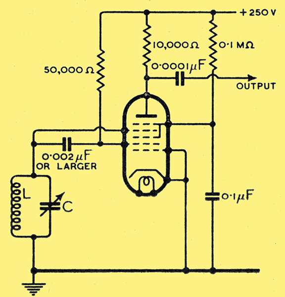
Transitron oscillator circuit with heptode valve (Osram X63, American 6A7, etc.).
I was very interested in recent Wireless World articles on the Transitron Oscillator, as I have been using a similar circuit for some years. However, two important improvements are embodied in my own circuit, shown in the accompanying diagram, which is used for heterodyne frequency meter work.
First, all who have had practical experience of any form of RF oscillator will appreciate the advantages obtained by having one end of the LC circuit at earth potential to both DC and RF. Secondly, one very important feature of the Dow or ECO circuit, as it is commonly employed, is that the output is usually obtained from the anode circuit load, the coupling between this and the frequency determining circuit being via the electron stream of the valve. These two important advantages can be embodied in the Transitron oscillator if a heptode valve is substituted for the RF pentode shown by Mr Chambers. In general, the upper frequency limit of oscillation of the Transitron and similar circuits is limited by the electron transit time, and in the case of the X63 and similar heptodes this limit lies between 30 and 40 MHz. I have no experience of the limits that may be reached with heptodes especially designed for UHF work.
It may be added that if a resistance is substituted for the LC circuit, it then becomes a current controlled relaxation oscillator, that will oscillate at an audio frequency continuously variable by varying the resistance. If such use is intended it will be advisable to increase the value of the screen-suppressor coupling condenser to, say, 0.1 μF. in order that the reactance may be small compared to the grid leak resistance to transmit satisfactorily the lowest frequency to be used. The circuit will then work satisfactorily down to a few Hz.
|